


LP5036 RGB Driver: 7 Checks for Color, Brightness and Dithered PWM

LP5036 RGB Driver: 7 Checks for Color, Brightness and Dithered PWM
Plan LP5036 RGB lighting with separate color and brightness controls, bank ownership, dithered PWM and a realistic total-current budget. This is a documentation-based planning guide, not a report of independent hands-on testing.
1. Map current sinks to twelve RGB groups
The LP5036 provides 36 constant-current sink outputs, enough for twelve three-channel RGB groups. This is the opposite output arrangement from a high-side current-source driver. Confirm LED polarity, LED supply, logic supply and the exact package wiring before assembly. Every group of three consecutive outputs shares an intensity-control register, so the physical color order matters to firmware. Build a channel map from OUT0 onward rather than assuming a board connector follows the color sequence used in an example program. Manufacturer documentation.
2. Keep color mixing separate from group brightness
Individual color-mixing registers are eight-bit controls, while each RGB group has a separate eight-bit brightness register. The effective duty derives from the interaction of those controls, not a single unrestricted twelve-bit software value. Hold brightness constant while checking red, green and blue individually; then change brightness while preserving the color ratios. This isolates mapping mistakes from dimming behavior. Save both sets of registers, because a correct color code can still appear wrong when the associated group brightness is unexpectedly reduced. Manufacturer documentation.
3. Understand what twelve-bit PWM means here
TI describes twelve-bit duty-control accuracy implemented with nine bits of pure PWM and three bits of digital dithering. With dithering disabled, the documented accuracy becomes nine bits. The PWM switching frequency is 29 kilohertz, but dithering distributes finer average values across multiple pulses. A single captured pulse therefore does not necessarily represent the long-term duty at a low code. Define an observation window that covers the pattern before comparing measured average light output with the intended setting. Manufacturer documentation.
4. Make bank ownership explicit before writing colors
The bank-control mechanism can replace individual color and brightness settings for selected LED groups. Once a group is assigned to bank control, changing its own color-mixing registers does not determine the output in the same way as independent mode. Record each bank-enable bit along with bank color and brightness values. Start with one group in independent mode, verify it, and only then enable shared control. Bank registers simplify coordinated effects; they are not a substitute for a documented output-ownership map. Manufacturer documentation.
Newest in the store


5. Set current from the actual supply and resistor
A single IREF resistor establishes the maximum constant-current setting. The normal maximum-current option supports up to 25.5 milliamps per channel across the specified VCC range; the 35-milliamp option requires VCC at least 3.3 volts and the corresponding configuration bit. Check LED ratings and output headroom before selecting either. Thirty-six channels at 25.5 milliamps represent 918 milliamps of simultaneous nominal LED demand. PWM phase shifting can redistribute switching activity, but it does not erase the total average-current and thermal budget. Manufacturer documentation.
6. Distinguish register retention from hardware shutdown
Software standby and automatic power save retain register data under their documented conditions. Hardware enable and initialization behavior must be considered separately: returning through initialization resets registers. Automatic power save requires its enable bit and all outputs inactive for more than thirty milliseconds; an I2C command wakes the device back into normal operation. Do not promise a particular idle current while a host continuously polls it. Verify the complete host traffic pattern and restore the intended register image after any reset event. Manufacturer documentation.
7. Qualify patterns with electrical and optical records
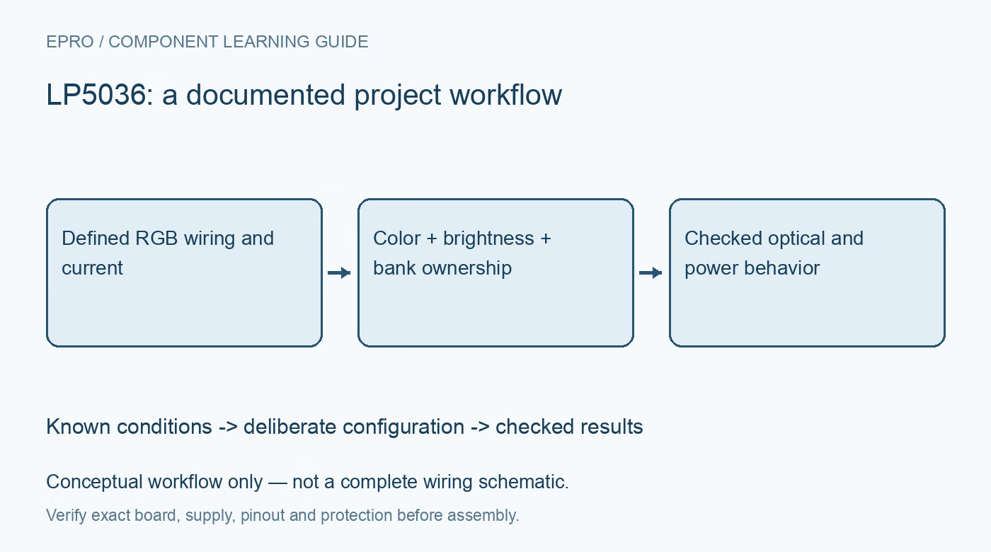
Use a current-limited low-voltage source and begin with one LED group at a conservative current. Check color order, dimming mode, bank transitions and supply behavior before enabling all outputs. Record IREF, maximum-current option, color values, brightness values, dithering and bank assignments together. Observe temperature and source droop during the highest simultaneous demand. Mark calculated expectations separately from actual measurements. A visually smooth animation is useful evidence about the effect, but it does not establish worst-case LED current or thermal margin. Manufacturer documentation.
Related reading: LP55231 LED Driver: 7 Checks for Shared Program Memory and High-Side Outputs.
Catalog note: The exact-part search did not return a matching Epro listing during preparation. Check the current catalog; this guide makes no price, availability or included-accessory claim.