


TMUX1574 Signal Switch: 7 Checks for Active-Low Enable and Powered-Off Protection

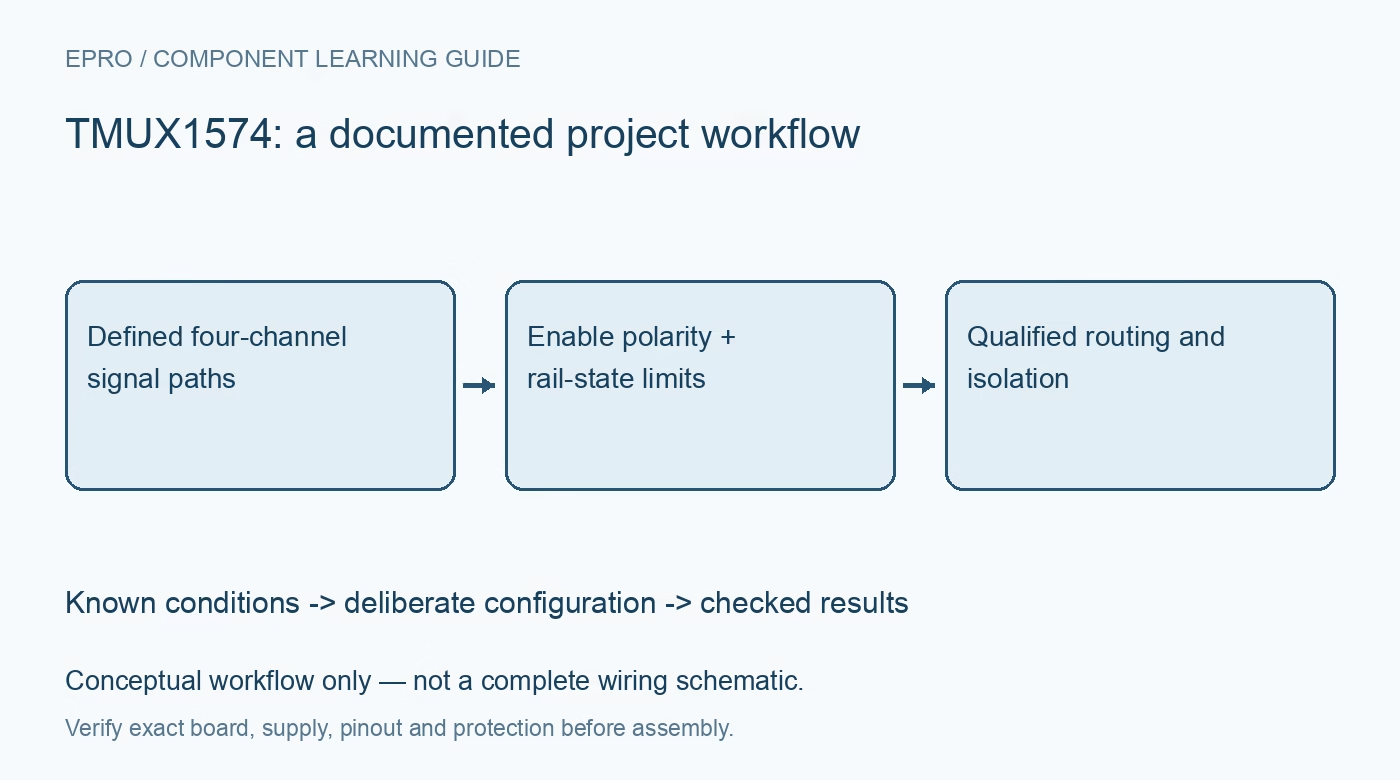
TMUX1574 Signal Switch: 7 Checks for Active-Low Enable and Powered-Off Protection
Use TMUX1574 with correct active-low enable, shared selection, powered-off signal limits and realistic high-speed routing. This is a documentation-based planning guide, not a report of independent hands-on testing.
1. Map four switches sharing one selection
TMUX1574 contains four bidirectional two-to-one signal paths. One shared selection signal chooses the A or B side across all four channels; it cannot independently select different destinations for each lane. Draw a source-to-drain map for the exact package and mark which external devices can actively drive each net. This matters when switching interfaces with mixed signal directions. The switch routes existing signals and does not provide voltage translation, bus arbitration or protocol-aware collision prevention. Manufacturer documentation.
2. Treat EN as an active-low control
The truth table is unambiguous: EN low permits the selected paths to conduct, while EN high makes them high impedance. With EN low, SEL low selects the A paths and SEL high selects the B paths. The logic pins include internal pulldowns, so a disconnected control is not a guaranteed disabled state. If isolation is required during controller reset, provide an explicit, compatible EN bias and validate it during the complete power-up sequence. Manufacturer documentation.
3. Apply the powered-on signal ceiling correctly
The supply range is 1.5V to 5.5V. With a valid supply, the recommended signal range extends to twice VDD but is also capped at 5.5V. Both conditions apply simultaneously: the twice-supply statement is not permission to route 11V at a 5.5V supply. Check every source and destination voltage, including idle-high pullups and startup transients. Signals are referenced to the switch ground and must not be treated as arbitrary bipolar analog inputs. Manufacturer documentation.
4. Separate powered-off and powered-on limits
When the switch supply is below 1.5V, the documented signal-path range is limited to 0V through 3.6V. Powered-off protection therefore does not authorize a 5V signal to remain present while the device loses power. Build a rail-state table covering fully powered, ramping, brownout and off conditions. Distinguish signal-path protection from fail-safe logic on the control pins. Verify leakage and downstream rail behavior in the allowed states instead of assuming that high impedance means perfect electrical isolation. Manufacturer documentation.
Newest in the store


5. Quiesce the interface before changing routes
An analog switch does not understand a SPI command, JTAG sequence or memory transaction. Arrange handover so active transmitters stop driving before a new route is selected, and allow the documented switching time before resuming communication. Use the enable state to establish isolation when the system architecture requires it. Include any external pullups or pulldowns in the idle-state analysis. A clean selection edge on the controller does not by itself prove that neither endpoint sees an unwanted pulse. Manufacturer documentation.
6. Evaluate bandwidth in the real interconnect
The approximately 2GHz bandwidth and low on-resistance are component characteristics under defined test conditions, not a guaranteed system data rate. Packages, connectors, trace stubs, return paths and receiver capacitance can dominate the result. Keep branches short and route high-speed lanes with an appropriate reference plane. Inspect the received waveform and timing margin using representative cable and board conditions. For low-frequency analog use, evaluate resistance-related gain error, leakage and charge injection rather than relying only on the bandwidth headline. Manufacturer documentation.
7. Preserve a rail-state validation matrix
Test both selections and the disabled state at bounded signal amplitudes, then repeat relevant cases during permitted supply transitions. Log the supply, endpoint rails, EN, SEL, signal amplitude, load and observed leakage or waveform change. An unpowered endpoint can introduce back-power paths outside the switch, so inspect the whole connection rather than only one pin. Keep the resulting scope captures and current measurements as project evidence; this guide supplies the checks, not a claim that a specific assembled board passed them. Manufacturer documentation.
Related reading: TMUX1136 Analog Switch: 7 Checks for Feedback Switching and Break-Before-Make.
Catalog note: The exact-part search did not return a matching Epro listing during preparation. Check the current catalog; this guide makes no price, availability or included-accessory claim.