


TMUX1136 Analog Switch: 7 Checks for Feedback Switching and Break-Before-Make

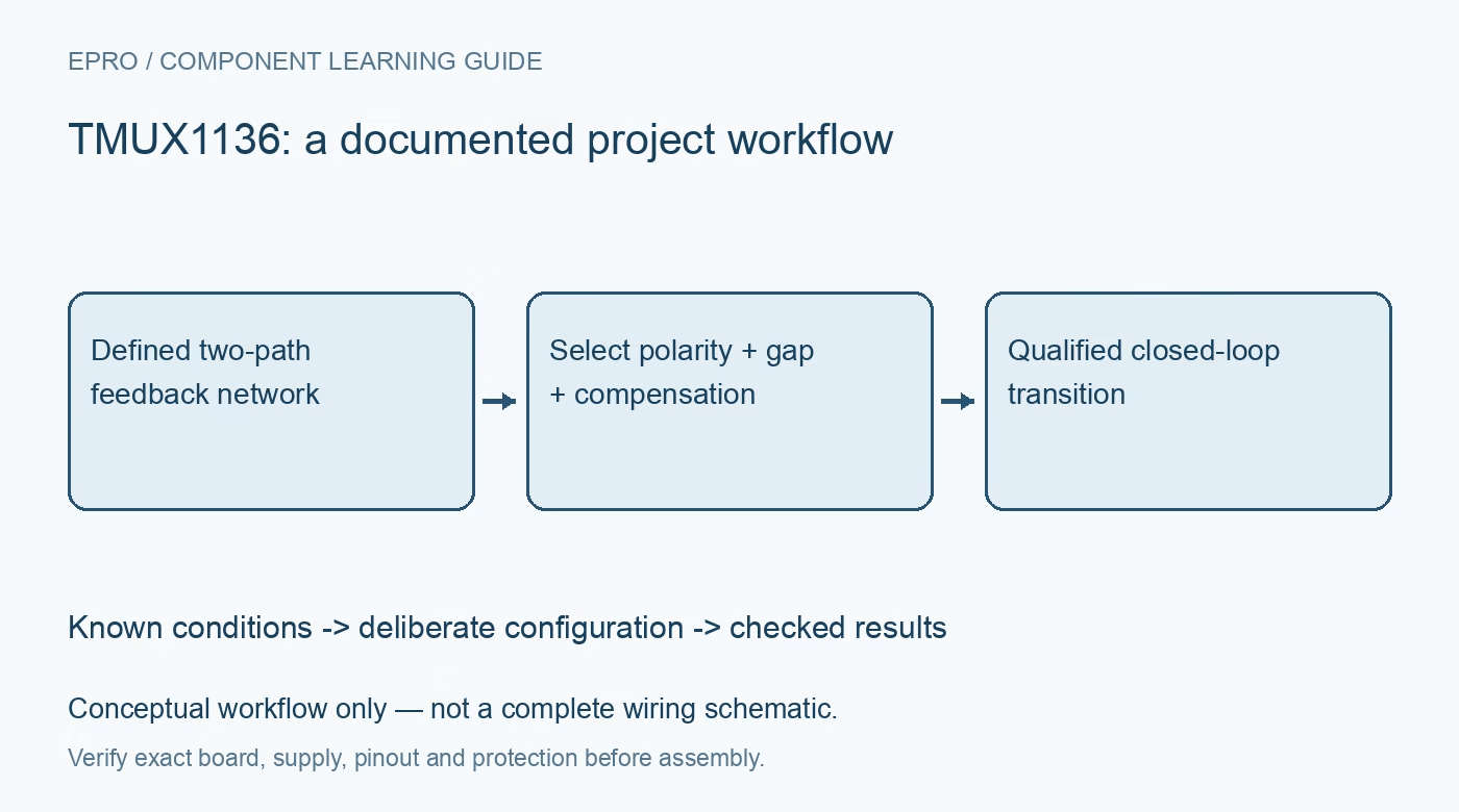
TMUX1136 Analog Switch: 7 Checks for Feedback Switching and Break-Before-Make
Qualify TMUX1136 dual SPDT feedback paths with the correct select polarity, break-before-make gaps, signal limits and amplifier settling. This is a documentation-based planning guide, not a report of independent hands-on testing.
1. Identify two independent SPDT paths
The TMUX1136 contains two independently controlled two-to-one analog switches. It is not a single four-input multiplexer and does not provide one shared address selecting both paths automatically. Make a table for S1A, S1B, D1, S2A, S2B, D2 and their select pins using the actual package drawing. The paths conduct bidirectionally within their limits. If both channels must change together in a feedback network, design that coordination explicitly rather than assuming that sharing a package makes their transitions perfectly simultaneous. Manufacturer documentation.
2. Check that high selects A and low selects B
For each channel, select low connects the B source to its drain, while select high connects the A source. These labels are easy to reverse when naming firmware ranges. Verify both states with a bounded signal before placing the switch inside an amplifier loop. Define the select level during controller reset and supply ramping. Also note that neither select state is a general all-off command: one of the two sources is normally selected, apart from the specified transition interval. Manufacturer documentation.
3. Keep analog protection separate from fail-safe logic
The supply range is 1.08 to 5.5 volts, and valid analog signals lie between ground and VDD. Fail-safe select logic allows control-pin voltages under separately specified conditions before supply establishment, but it does not permit arbitrary powered-off analog voltages. Evaluate every terminal during startup and source removal. A feedback node that sits safely near midscale in normal operation may be driven outside the switch rails if the amplifier saturates or another supply disappears. Check those states before assuming a logic-low command provides isolation. Manufacturer documentation.
4. Analyze the break-before-make interval in the loop
Break-before-make behavior avoids momentarily shorting the two selected sources together, but it also creates an interval when neither path conducts. In an amplifier feedback application, that interval can temporarily remove the intended feedback path. Determine what holds the loop stable and bounds the output during the change. Do not replace this analysis with the statement that break-before-make is always safer. A topology may need a separately designed permanent path, sequencing arrangement or controlled acquisition pause to avoid overload and long recovery. Manufacturer documentation.
Newest in the store


5. Include resistance, leakage and charge injection
On-resistance changes the effective network and can introduce gain error if treated as zero. Leakage affects high-impedance nodes, while control transitions inject charge into capacitance. The typical minus-six-picocoulomb charge-injection headline is characterized under stated conditions and is not a fixed voltage correction. As an illustration, six picocoulombs on one nanofarad corresponds to six millivolts before the surrounding network responds. Check the actual signal voltage, capacitance and impedance, and keep typical device figures separate from guaranteed complete-circuit error bounds. Manufacturer documentation.
6. Validate compensation and settling in both states
Each feedback setting changes not only nominal gain but also loop dynamics and noise gain. Review amplifier stability with the selected resistor-capacitor network, switch parasitics and sensor capacitance. After switching, allow the complete signal path to settle to a defined error band before accepting an ADC result. A fast digital select edge is not evidence of immediate analog validity. Include transitions in both directions and from realistic initial conditions, because the larger step or temporarily overloaded state may govern the required recovery time. Manufacturer documentation.
7. Preserve a transition-aware configuration record
Record the two network states, select polarity, rail values, component tolerances and allowed acquisition pause. With current-limited low-voltage supplies and a benign source, capture selects and amplifier output through repeated transitions. Check for peaking, clipping and unexpected interaction between channels before connecting a sensitive sensor. Distinguish calculations, datasheet expectations and observed waveforms. Acceptance should cover valid closed-loop behavior through the entire range change, not simply show that both final static gains are correct after the circuit has had ample time to recover. Manufacturer documentation.
Related reading: TMUX4051 Analog Mux: 7 Checks for Bipolar Rails and ADC Boundaries.
Catalog note: The exact-part search did not return a matching Epro listing during preparation. Check the current catalog; this guide makes no price, availability or included-accessory claim.