


THVD1450 RS-485 Transceiver: 7 Checks for Direction Timing and Failsafe Meaning

THVD1450 RS-485 Transceiver: 7 Checks for Direction Timing and Failsafe Meaning
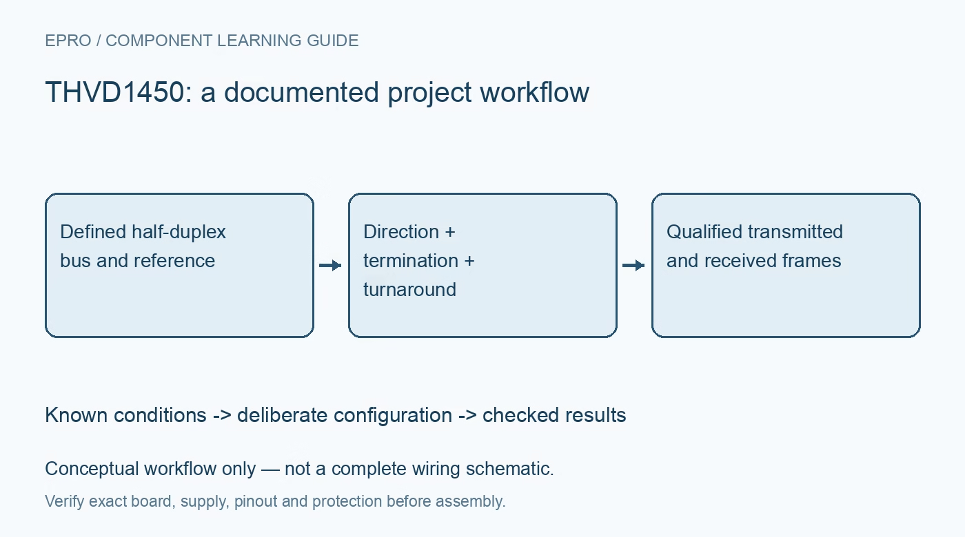
Plan THVD1450 half-duplex links with explicit DE and receiver-enable states, bus polarity, termination, common-mode limits and turnaround timing. This is a documentation-based planning guide, not a report of independent hands-on testing.
1. Define a half-duplex physical link, not a protocol
The THVD1450 is a half-duplex RS-485 transceiver operating from three to 5.5 volts, with a data-rate capability up to fifty megabits per second under the specified conditions. It does not implement packet addressing, arbitration, error recovery or an isolation barrier. State the intended baud rate, cable topology, node count and communication protocol separately. Begin with two nodes on a short, controlled low-voltage bench link before claiming performance over long cables or in a noisy installation. Manufacturer documentation.
2. Use the exact direction-control polarities
DE high enables the differential driver; DE low makes its bus outputs high impedance. The receiver-enable input is active low: low enables R, while high or open makes R high impedance. Internal default biasing does not replace a deliberate controller startup design. Define who may drive the bus during reset and how the receiving UART input is held when the receiver is disabled. A half-duplex system needs explicit ownership rules; two valid transceivers can still contend if firmware enables both drivers together. Manufacturer documentation.
3. Confirm differential polarity without relying on connector names
For this device, a high D input drives A above B, giving positive VA minus VB; a low D input reverses that differential voltage. Some system documentation and third-party modules use inconsistent A/B naming conventions. Verify the actual relationship with a known pattern rather than swapping labels based on an assumption. Check UART inversion settings and the receiving logic state independently. A link that accidentally works with one module can fail when a differently labeled module is substituted later. Manufacturer documentation.
4. Treat failsafe high as an electrical state, not health
With the receiver enabled, internal failsafe behavior produces a high output for the documented open, shorted or idle bus conditions. A high R signal therefore does not prove that the cable is intact or that a remote controller is running. Use framing checks, timeouts and any required application-level integrity check to establish valid communication. Failsafe biasing also does not replace appropriate termination or make a disabled receiver output actively high. Interpret R together with direction state and expected traffic. Manufacturer documentation.
Newest in the store


5. Match termination and common-mode requirements to the installation
Use a controlled transmission-line topology with appropriate end termination and short stubs, considering actual edge speed rather than baud rate alone. Do not put a terminating resistor at every node by default. The extended common-mode range is not permission for unlimited ground differences, and ESD protection is not galvanic isolation or a complete surge solution. Review the cable reference path and system protection separately. Avoid connecting the bench prototype to building wiring or an unknown remotely grounded installation without a suitable system-level assessment. Manufacturer documentation.
6. Time turnaround from the last transmitted bit
The controller must keep DE active until the UART has finished the final stop bit, not merely until software has copied the last byte into a transmit buffer. Include driver enable and disable timing before releasing the line and accepting a response. Capture D, DE and the differential bus together to verify the real interval. Excessive overlap risks contention, while releasing too early truncates a frame. Define a recovery policy for interrupted transmissions rather than assuming a fixed delay works at every baud rate. Manufacturer documentation.
7. Qualify frames and electrical margins separately
Record supply, baud rate, topology, cable, termination, control states and receiver loading. On the bounded two-node setup, test repeated requests, replies, deliberate idle and controlled reset of either endpoint. Check complete frame delivery as well as differential levels and edge quality. Mark measured results separately from manufacturer limits and theoretical cable expectations. A short successful message does not establish a fifty-megabit long-distance link, immunity to every transient, or reliable protocol behavior when a node resets while owning the bus. Manufacturer documentation.
Related reading: MAX485 Arduino: Two-Node RS485 Wiring and Bring-Up.
Catalog note: The exact-part search did not return a matching Epro listing during preparation. Check the current catalog; this guide makes no price, availability or included-accessory claim.