


TPS2113A Power Mux: 7 Checks for Priority Thresholds and Status Ambiguity

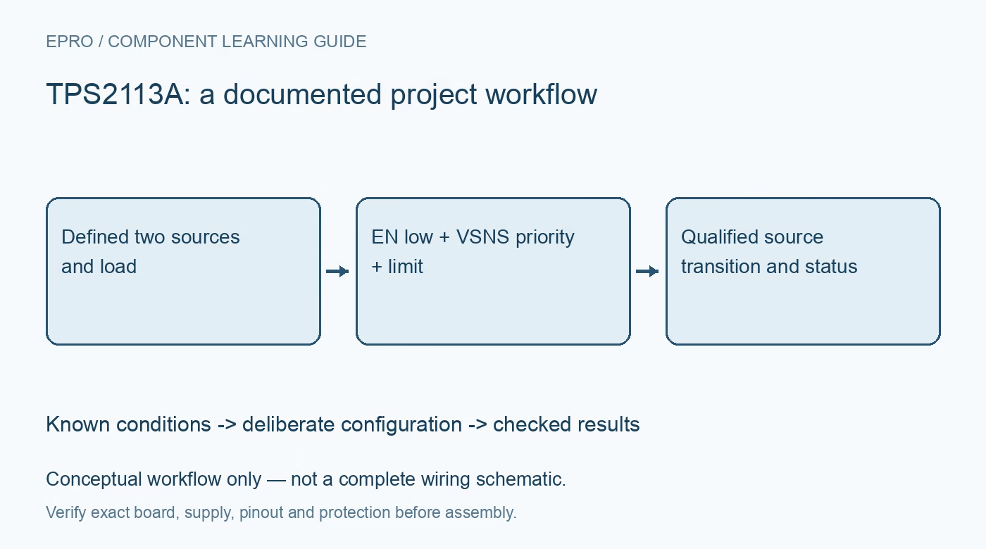
TPS2113A Power Mux: 7 Checks for Priority Thresholds and Status Ambiguity
Check TPS2113A active-low enable, VSNS priority logic, STAT meaning, current-limit scaling and output hold-up during source changes. This is a documentation-based planning guide, not a report of independent hands-on testing.
1. Define the two source envelopes and package
The TPS2113A selects between two inputs operating in the 2.8-to-5.5-volt range. Identify their tolerances, source impedances, removal behavior and load demand before choosing a connection policy. Current capability and thermal performance depend on package and conditions; the family headline is not a universal two-amp guarantee. Use current-limited low-voltage sources for initial testing, with no accidental connection between independently powered outputs. A power multiplexer is not a battery charger or a substitute for the protection required by a particular battery chemistry. Manufacturer documentation.
2. Read EN as an active-low operating control
The truth table enables source selection when EN is low. Driving EN high puts OUT into the high-impedance state, subject to the documented behavior, and an internal pullup influences an unconnected control. Do not copy an active-high enable assumption from another load switch. Define EN during controller reset and source startup, then check its actual logic thresholds. A rail that fails to appear may be correctly disabled rather than suffering an input-selection fault, so inspect control state before changing source wiring. Manufacturer documentation.
3. Separate primary preference from higher-voltage selection
When enabled and VSNS exceeds the nominal 0.8-volt threshold, the device selects IN1, provided the relevant undervoltage conditions permit it. Otherwise, it selects the higher of IN1 and IN2. Low VSNS does not simply force IN2. Set the sensing divider from the desired primary-source threshold and include threshold tolerance, divider tolerance and the documented hysteresis. Verify the policy across overlapping input voltages rather than testing only one primary-high and one primary-absent case. Manufacturer documentation.
4. Avoid treating STAT low as proof of primary power
STAT is open drain and releases when the IN2 switch is on. It pulls low when IN1 is selected and also when OUT is high impedance in the disabled state. Thus, a low indication alone does not prove the load is powered from IN1. Add a suitable pullup and interpret status with EN, input voltages and the actual output condition. If uninterrupted operation matters, monitor the load rail directly rather than assigning a power-good meaning to a source-status output. Manufacturer documentation.
Newest in the store


5. Use the correct current-limit coefficient
The nominal TPS2113A current-limit relationship is 500 divided by RILIM with the units and conditions given in the datasheet; the neighboring TPS2112A uses a different coefficient. A nominal one-kilohm resistor therefore corresponds to 0.5 amp before tolerance and operating-condition effects are considered. Do not short ILIM to ground as a way to obtain a small limit: TI warns that zero resistance disables current limiting. Check startup load, current-limit accuracy and thermal dissipation together instead of relying on the nominal resistor calculation alone. Manufacturer documentation.
6. Analyze hold-up and reverse behavior during transitions
The device prevents both source switches conducting simultaneously and delays a connection to a lower source until the output has fallen close enough under the documented conditions. The datasheet also states that, once connected, a supply remains connected regardless of output voltage. Do not turn the reverse-conduction headline into a claim of unconditional continuously active ideal-diode behavior. Size output hold-up and evaluate permissible droop with the real load. Slew from a disabled state and source-to-source transitions also have different documented behavior. Manufacturer documentation.
7. Validate the complete source-state matrix
Test IN1 only, IN2 only, both present, controlled primary droop, disabled output and recovery using bounded current-limited supplies. Record divider values, current-limit resistor, package, capacitance, source impedance and load profile. Capture both inputs, OUT, EN and status through changes, looking for repeated switching or unintended resets. Keep measured waveforms separate from nominal calculations. Acceptance should demonstrate the intended selection policy and load-voltage continuity, not merely show that the output eventually reaches one of the available source voltages. Manufacturer documentation.
Related reading: TPS2116 Power Mux: 7 Checks for Priority and Break-Before-Make.
Catalog note: The exact-part search did not return a matching Epro listing during preparation. Check the current catalog; this guide makes no price, availability or included-accessory claim.