


THVD1420 RS-485 Transceiver: 7 Checks for 12Mbps Links and Safe Turnaround

THVD1420 RS-485 Transceiver: 7 Checks for 12Mbps Links and Safe Turnaround
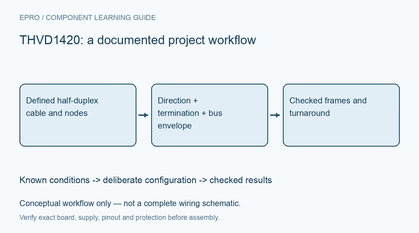
Plan THVD1420 half-duplex links with correct direction timing, bus limits, termination and meaningful failsafe diagnostics. This is a documentation-based planning guide, not a report of independent hands-on testing.
1. Distinguish the 12Mbps family member
THVD1420 is the 12Mbps member of the documented family; the closely named THVD1400 is specified for 500kbps. Confirm the marking and ordering code before using timing assumptions copied from a different board. The supply range is 3V to 5.5V, and the interface is half duplex. A headline maximum data rate does not specify a maximum cable length for every installation. Cable loss, topology, noise and timing margin must be evaluated together. Manufacturer documentation.
2. Make direction control a timed operation
DE high enables the bus driver, while the active-low receiver-enable input controls whether the receiver output drives the controller. Define both pins during boot and reset so the node does not seize the bus unexpectedly. Wait for the final stop bit to leave the transmitter before disabling the driver, then allow the documented disable and enable delays during turnaround. A transmit-buffer-empty flag can occur before the physical transmission is complete; use the controller status that actually represents completion. Manufacturer documentation.
3. Verify polarity from the differential definition
Check the datasheet truth table and connector wiring rather than relying on inconsistent A and B labels across third-party modules. Send a known pattern on a short, controlled link and inspect the differential bus voltage and received logic. Record the polarity mapping in the connector documentation so replacing a module does not invert the link silently. Do not try to correct a wiring error by changing unrelated serial framing settings, because an apparently occasional response can conceal a fundamentally incorrect differential connection. Manufacturer documentation.
4. Design termination for the cable topology
Use the cable characteristic impedance and physical endpoints to decide where termination belongs. Adding a termination resistor at every node increases loading and can make a working short link fail when expanded. Keep branch stubs short relative to edge timing and account for connector and cable discontinuities. The one-eighth-unit-load receiver rating supports many nodes under specified loading assumptions; it does not override the combined effects of termination, external biasing and real wiring. Inspect a representative populated bus, not only a single-node demonstration. Manufacturer documentation.
Newest in the store


5. Keep fault tolerance separate from operation
The bus fault-protection headline includes an absolute-maximum voltage rating, which is not the receiver common-mode operating range. Stay within the recommended operating conditions for valid communication and separately assess abnormal ground offsets and external transients. The transceiver is not an isolation barrier. If the system needs isolation, surge protection or a safety-rated ground separation, implement those deliberately. ESD qualification at the component level does not certify a finished cable installation or make exposed wiring safe to touch. Manufacturer documentation.
6. Interpret failsafe as an idle logic result
Open, short and idle-bus failsafe behavior provides a defined receiver tendency under the documented conditions. A high receiver output does not prove that the cable is connected, the remote device is powered or the protocol exchange is healthy. Add frame validation, timeouts and application-level sequence or integrity checks. When the receiver is disabled its output is high impedance, which requires separate consideration at the controller input. Distinguish this state from an actively driven failsafe output when diagnosing an idle line. Manufacturer documentation.
7. Validate turnaround under realistic loading
Start with low-energy bench supplies, a short cable and conservative baud rate before expanding toward the intended installation. Test request-response timing, missing nodes, permitted power cycling and the fully populated termination arrangement. Capture DE, receiver enable, serial data and differential voltage together when possible. Preserve cable type, length, topology, baud rate, supply and error counts with each run. A zero-error short demonstration is useful evidence for that setup only, not a blanket guarantee for every 12Mbps network. Manufacturer documentation.
Related reading: THVD1450 RS-485 Transceiver: 7 Checks for Direction Timing and Failsafe Meaning.
Catalog note: The exact-part search did not return a matching Epro listing during preparation. Check the current catalog; this guide makes no price, availability or included-accessory claim.