


REF5025 Voltage Reference: 7 Checks for Grade, Pinout and Real Error Budgets

REF5025 Voltage Reference: 7 Checks for Grade, Pinout and Real Error Budgets
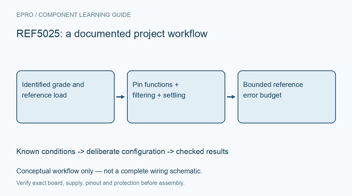
Distinguish REF5025 grades and pin functions before budgeting accuracy, filtering, startup, ADC loading and temperature drift. This is a documentation-based planning guide, not a report of independent hands-on testing.
1. Identify the complete grade and revision
The current REF50 family documentation includes standard, high and enhanced grades, with different specifications and some different pin functions. Identify the full REF5025 ordering code and package before borrowing a schematic or accuracy number. The nominal output is 2.5V, but a shared nominal voltage does not make every grade electrically identical. Save the manufacturer document revision with the bill of materials, especially when a newly introduced grade appears beside legacy versions in the same datasheet. Manufacturer documentation.
2. Do not interchange DNC and enable pins
For the legacy standard and high grades, pin 1 is marked do not connect, while the enhanced grade uses that position for EN. Pin 5 is TRIM/NR on the legacy versions but NR on the enhanced version. A board that drives or trims these pins must therefore be checked against the exact fitted device. Do not connect a do-not-connect pin merely because another variant uses it. Treat a grade substitution as a design review, not simply a purchasing substitution. Manufacturer documentation.
3. Keep accuracy specifications grade-specific
The documented maximum initial errors are 0.1% for standard grade, 0.05% for high grade and 0.025% for enhanced grade. At 2.5V these correspond to 2.5mV, 1.25mV and 0.625mV respectively before other system errors. Drift limits are also grade-dependent. Use the correct row and test conditions rather than combining the best numbers from different versions. Initial accuracy, temperature behavior, long-term drift and calibration residuals belong in separate entries of an error budget. Manufacturer documentation.
4. Check headroom and output loading
A reference is not a general-purpose power rail. Review input headroom, allowed input voltage and sourcing or sinking capability for the chosen grade and operating temperature. The enhanced version has a different maximum input-voltage capability from the legacy grades; do not apply the higher value universally. Include load regulation and dissipation in the assessment. Start from a protected low-voltage source with adequate margin, then measure at the actual reference load rather than treating an unloaded meter reading as the complete result. Manufacturer documentation.
Newest in the store


5. Select capacitors from the correct guidance
Noise reduction, output stability and startup are linked but not interchangeable. Follow the capacitor and ESR guidance for the actual grade rather than assuming every precision reference prefers the lowest possible ESR. On legacy TRIM/NR versions, added capacitance can reduce noise while extending startup. The enhanced version uses a dedicated NR function and different electrical tables. Record capacitance, dielectric, effective capacitance and any series resistance so later measurements can be interpreted against the intended circuit rather than an unspecified breakout-board population. Manufacturer documentation.
6. Qualify the ADC sampling load
An ADC reference input can draw transient charging current even when its average current appears small. Inspect the reference node close to the converter during actual conversions and evaluate local decoupling, trace impedance and any buffer required by the converter documentation. An extra RC filter can reduce some noise while increasing settling error under a dynamic load. Compare the acquisition conditions with the reference response instead of choosing a capacitor solely from a low-frequency noise target. Manufacturer documentation.
7. Separate measured error from instrument uncertainty
Measure after a documented warmup and settling interval, using equipment whose uncertainty is meaningful at the intended accuracy. Record temperature, grade, supply, load, capacitor network and instrument calibration status. A single room-temperature adjustment cannot establish drift over the full operating range or predict aging. Preserve repeated measurements and uncertainty estimates rather than displaying more decimal places as evidence of precision. The outcome should be a bounded reference contribution to the system error budget, not an unsupported claim that every assembled board achieves the headline accuracy. Manufacturer documentation.
Related reading: REF3425 Voltage Reference: 7 Checks for Kelvin Routing and Real Accuracy.
Catalog note: The exact-part search did not return a matching Epro listing during preparation. Check the current catalog; this guide makes no price, availability or included-accessory claim.