


REF3425 Voltage Reference: 7 Checks for Kelvin Routing and Real Accuracy

REF3425 Voltage Reference: 7 Checks for Kelvin Routing and Real Accuracy
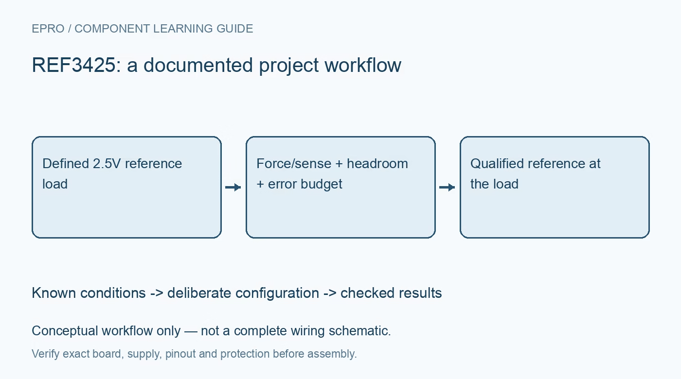
Budget REF3425 accuracy with force-and-sense routing, loaded dropout, source and sink demand, startup capacitance and bandwidth-qualified noise. This is a documentation-based planning guide, not a report of independent hands-on testing.
1. Confirm the exact pinout and reference voltage
REF3425 is the 2.5-volt member of the REF34 family. The standard version has output-force, output-sense, ground-force, ground-sense and enable connections, while the related T pinout omits those same feature assignments. Similar six-pin packaging is not proof of interchangeable wiring. Verify the complete orderable part and top-view drawing before connecting it. Define the ADC or DAC reference load separately from the logic supply; a precision reference is not automatically an appropriate general-purpose rail for unrelated digital circuitry. Manufacturer documentation.
2. Sense voltage where the accuracy is required
Force traces carry load current, while sense traces convey the load-side voltage with much smaller current. Connect the force and sense arrangements according to the manufacturer circuit, keeping their purpose explicit. A load-current drop in a shared ground return can be just as damaging as a drop in the positive reference trace. Do not leave sense pins floating. Where local force and sense ties are appropriate, place them deliberately rather than assuming a broad net name makes every point on the board electrically identical. Manufacturer documentation.
3. Budget initial error and drift separately
The family specifies maximum initial accuracy of plus or minus 0.05 percent and a maximum temperature coefficient of six parts per million per degree Celsius under the documented conditions. At 2.5 volts, 0.05 percent corresponds to 1.25 millivolts before other system errors. Temperature drift, thermal hysteresis, long-term change and board-level drops are separate contributions. Do not simply call the entire system a 0.05-percent instrument. Also distinguish a temperature-coefficient limit from a prediction that error varies as one perfectly linear slope through every temperature. Manufacturer documentation.
4. Use loaded dropout rather than the zero-load headline
Recommended input voltage must exceed the output by the relevant dropout requirement and remain within the input limit. A very low zero-load dropout number does not establish the same margin while sourcing milliamps. Check the electrical table and load conditions for the intended operating point, including supply ripple and temperature. A source that occasionally falls below the required headroom can turn reference movement into apparent sensor movement. Record minimum input at the reference pins rather than relying only on the nominal upstream supply label. Manufacturer documentation.
Newest in the store


5. Include source, sink and transient current demand
The reference supports source and sink current within specified limits, but thermal conditions and dynamic loading still matter. An ADC reference input can draw pulsed charge even when its average current seems small. Check the converter requirements, local capacitance and whether a suitable buffer is needed. Do not assume that staying below a ten-milliamp headline guarantees instant settling after every load event. Evaluate return paths and temperature as well, especially when a high input voltage increases internal dissipation while the reference sources current. Manufacturer documentation.
6. Tie capacitor choice to stability, noise and startup
The manufacturer requires at least 0.1 microfarad of ceramic output capacitance for improved stability and high-frequency filtering, with additional capacitance useful for transient response under its guidance. More capacitance also increases turn-on time. Check effective values, ESR and placement rather than copying a nominal bill of materials without context. Low-frequency noise figures have a stated bandwidth and scaling convention; they are not an unrestricted broadband noise guarantee. Establish how long the reference and receiving converter must settle before accepting readings after enable or supply startup. Manufacturer documentation.
7. Measure at the load and retain the conditions
Record the exact variant, force-and-sense routing, input range, load current, capacitances, temperature and measurement bandwidth. Use a suitable independent instrument to inspect steady-state voltage at the receiving device, not just at the reference output pin. Check startup and representative load changes with a bounded current-limited source. Label actual observations separately from ideal arithmetic and manufacturer limits. Acceptance should demonstrate a reference error budget at the point of use, rather than promise measurement accuracy solely from the component voltage printed on the schematic. Manufacturer documentation.
Related reading: REF3330 Voltage Reference: 7 Checks Before Treating 3 V as Precise.
Catalog note: The exact-part search did not return a matching Epro listing during preparation. Check the current catalog; this guide makes no price, availability or included-accessory claim.