


ADS8688A SAR ADC: 7 Checks for Bipolar Codes and Channel-Selection Frames

ADS8688A SAR ADC: 7 Checks for Bipolar Codes and Channel-Selection Frames
Check ADS8688A bipolar straight-binary codes, per-channel ranges, 32-clock command frames and the different limits of its auxiliary input. This is a documentation-based planning guide, not a report of independent hands-on testing.
1. Distinguish eight multiplexed channels from simultaneous sampling
The ADS8688A integrates eight conditioned analog input channels feeding a sixteen-bit SAR converter. Its 500-kilosample-per-second throughput is aggregate, not a simultaneous rate for every channel. Define the scan order and required per-channel cadence before designing timestamps. It uses a five-volt analog supply and a separate digital interface supply under the specified limits. Keep power domains, reference configuration and package connections explicit. Begin with safe bounded sources rather than connecting an unknown industrial signal simply because the input range can be bipolar. Manufacturer documentation.
2. Assign a range and ground reference to each channel
The main channels support several programmed bipolar and unipolar ranges, with the scale linked to the reference voltage. AIN_nGND is tied to ground in the documented single-ended arrangement; the pair is not a freely floating instrumentation input. Confirm the actual range register before applying a source. The input-protection headline is not the valid measurement range and does not qualify the board for surge, mains or isolated sensing. Check external filtering and protection separately, including the effect of a source that remains powered during ADC shutdown. Manufacturer documentation.
3. Decode bipolar results as straight binary
The output format is straight binary for both bipolar and unipolar ranges. In a bipolar range, midscale represents the nominal zero region; treating the word as signed two-complement data produces the wrong voltage mapping. For the plus-or-minus-10.24-volt range with the nominal reference, the full span is 20.48 volts and one code step is 312.5 microvolts. Derive the voltage from the configured negative endpoint plus code times span divided by 65536, while separately budgeting actual offset, gain and reference errors. Manufacturer documentation.
4. Track channel commands across frame boundaries
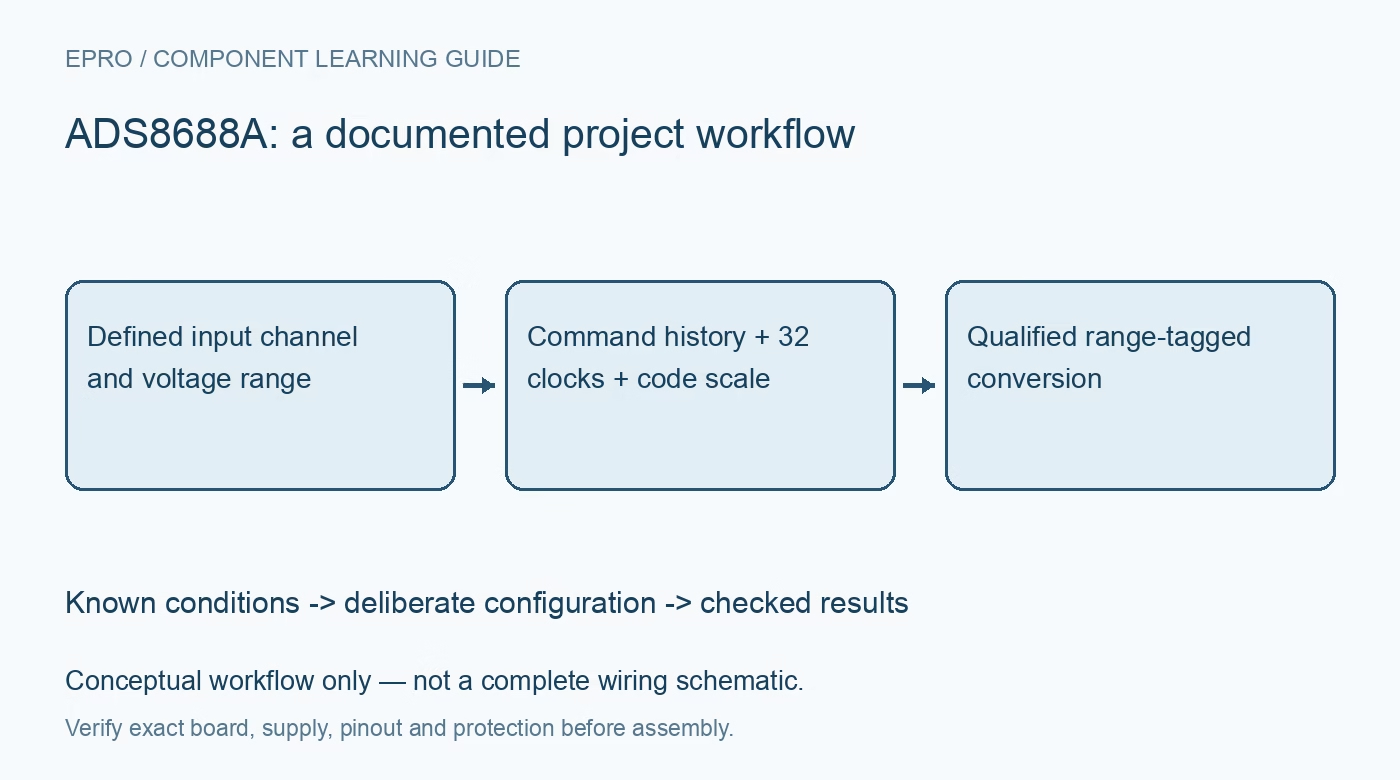
The analog channel sampled at the falling CS edge is selected by the previous data frame. A command transmitted now configures the subsequent conversion, rather than retroactively changing the sample already captured. At the same time, the conversion result for the current frame is shifted out after the documented conversion interval. Keep channel-command history and sample timestamps together in firmware. A constant test voltage can hide an off-by-one channel assignment, so validate the scan with deliberately different bounded voltages on neighboring channels. Manufacturer documentation.
Newest in the store


5. Keep complete timing even when a command is short
The manual-channel guidance requires a complete 32-SCLK frame to accurately acquire and convert the next selected channel. Sixteen output bits do not mean every transaction can be shortened to sixteen clocks. The first half of the frame carries the command and allows internal conversion; output data follow the specified clock edges. Respect the timing-table limit on clock frequency, including when the sixteenth edge may occur. Check CS, SDI, SDO and SCLK together rather than accepting plausible software words as proof of correct acquisition timing. Manufacturer documentation.
6. Treat AUX as a different analog path
The auxiliary input bypasses the conditioned front-end path used by the main channels. It supports only zero to VREF, with AUX_GND tied to ground, and directly drives an internal sampling capacitor. It does not inherit the main-channel bipolar range, constant input impedance or overvoltage assumptions. Source impedance, acquisition demand and an appropriate driver matter especially at higher rate. Label AUX separately in schematics and firmware so a spare connector is not casually reused for the same signal class as a protected main input. Manufacturer documentation.
7. Retain range and channel identity with every record
Save raw codes, range registers, reference configuration, scan commands and timestamps. Check several known levels in unipolar and bipolar modes, then verify channel transitions and any AUX measurements independently. Include source impedance and sampling cadence in the acceptance conditions. Distinguish calculated ideal code values from observations and specification limits. A trustworthy acquisition record shows which input and range produced each conversion, not merely a list of sixteen-bit words that appears numerically stable when every connected source happens to be constant. Manufacturer documentation.
Related reading: ADS8681 SAR ADC: 7 Checks for Bipolar Range and Code Mapping.
Catalog note: The exact-part search did not return a matching Epro listing during preparation. Check the current catalog; this guide makes no price, availability or included-accessory claim.