


TPS22992 Load Switch: 7 Checks for Variant Protection and CT Voltage

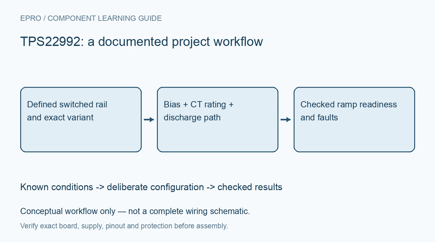
TPS22992 Load Switch: 7 Checks for Variant Protection and CT Voltage
Review TPS22992 bias rails, TPS22992S-only fault protection, high-voltage CT behavior, power-good meaning and adjustable discharge. This is a documentation-based planning guide, not a report of independent hands-on testing.
1. Distinguish the base part from the S variant
TPS22992 and TPS22992S are related but not identical protection devices. The S version includes short-circuit protection, while that feature must not be assumed for the base part. Their minimum switched-input voltages also differ. Read the complete ordering code and inspect the board documentation before planning a fault response. A listing that omits the suffix is insufficient evidence. Keep the exact fitted variant in the bill of materials and beside the firmware sequencing assumptions. Manufacturer documentation.
2. Draw the bias and switched rails separately
VBIAS must remain within 1.5V to 5.5V. The recommended switched-input range extends from 0.1V to VBIAS for TPS22992, or from 1V to VBIAS for TPS22992S. A 5.5V headline therefore does not mean VIN may exceed the active bias supply. Document allowed sequencing and review every control voltage during brownout and shutdown. The device passes a rail through a controlled switch; it does not regulate an unsuitable source or provide arbitrary level conversion between power domains. Manufacturer documentation.
3. Rate CT for its internal voltage, not VIN
The slew-rate control pin is not confined to the low-voltage switched input. The datasheet notes that CT can reach 15V and specifies a minimum 30V capacitor rating for optimal performance. A small low-voltage ceramic selected only from a 3.3V system rail can therefore be inappropriate. Choose its voltage rating, effective capacitance and physical placement deliberately. Use the documented timing equations and conditions, then verify the actual ramp instead of assuming the printed capacitance alone predicts startup behavior. Manufacturer documentation.
4. Estimate inrush with the live load included
Capacitive inrush is approximately output capacitance multiplied by voltage rise rate, but a downstream load may begin consuming current before the ramp finishes. Add that behavior to the source-current budget and check input droop. A slower ramp may help the supply while extending the time spent at an intermediate voltage. For the base TPS22992, do not mistake controlled slew rate for short-circuit current limiting. Use a current-limited source and a benign load while establishing the startup envelope. Manufacturer documentation.
Newest in the store


5. Use PG as switch-readiness information
The open-drain PG signal indicates that the main MOSFET is fully on and its on-resistance is near the final value. It is not a precision indication that the downstream voltage meets an independent regulation threshold. Provide a compatible pullup and inspect the power conditions required for a valid flag. If a processor or converter needs a strict minimum rail voltage, qualify that separately. Record PG together with VIN and VOUT when validating a sequencing decision rather than observing the digital flag alone. Manufacturer documentation.
6. Configure the discharge path explicitly
The QOD pin can connect directly to VOUT, connect through an external resistor to slow discharge, or remain floating to omit quick output discharge. These choices produce different shutdown behavior. Check prebiased loads and other sources attached to VOUT before enabling a discharge path. Also review the smart ON pulldown: its behavior changes with the input state, so an uncontrolled high-impedance controller output should not be treated as a complete safety strategy. Drive defined states and test them across the intended power sequence. Manufacturer documentation.
7. Qualify current and thermal behavior conservatively
The 6A current headline and typical on-resistance depend on electrical and thermal conditions. Calculate conduction loss, inspect copper and connectors, and observe temperature using a bounded representative load. Thermal shutdown is a protective mechanism, not the normal operating setpoint. Fault testing on the S variant must remain within a reviewed low-energy setup and documented limits. Save the variant, rail sequence, CT rating, QOD connection, load and waveforms with the handover so later substitutions cannot silently invalidate the results. Manufacturer documentation.
Related reading: TPS22990 Load Switch: 7 Checks for Bias Rails, Power Good and Discharge.
Catalog note: The exact-part search did not return a matching Epro listing during preparation. Check the current catalog; this guide makes no price, availability or included-accessory claim.