


INA280 Current-Sense Amplifier: 7 Checks for Unidirectional High-Side Sensing

INA280 Current-Sense Amplifier: 7 Checks for Unidirectional High-Side Sensing
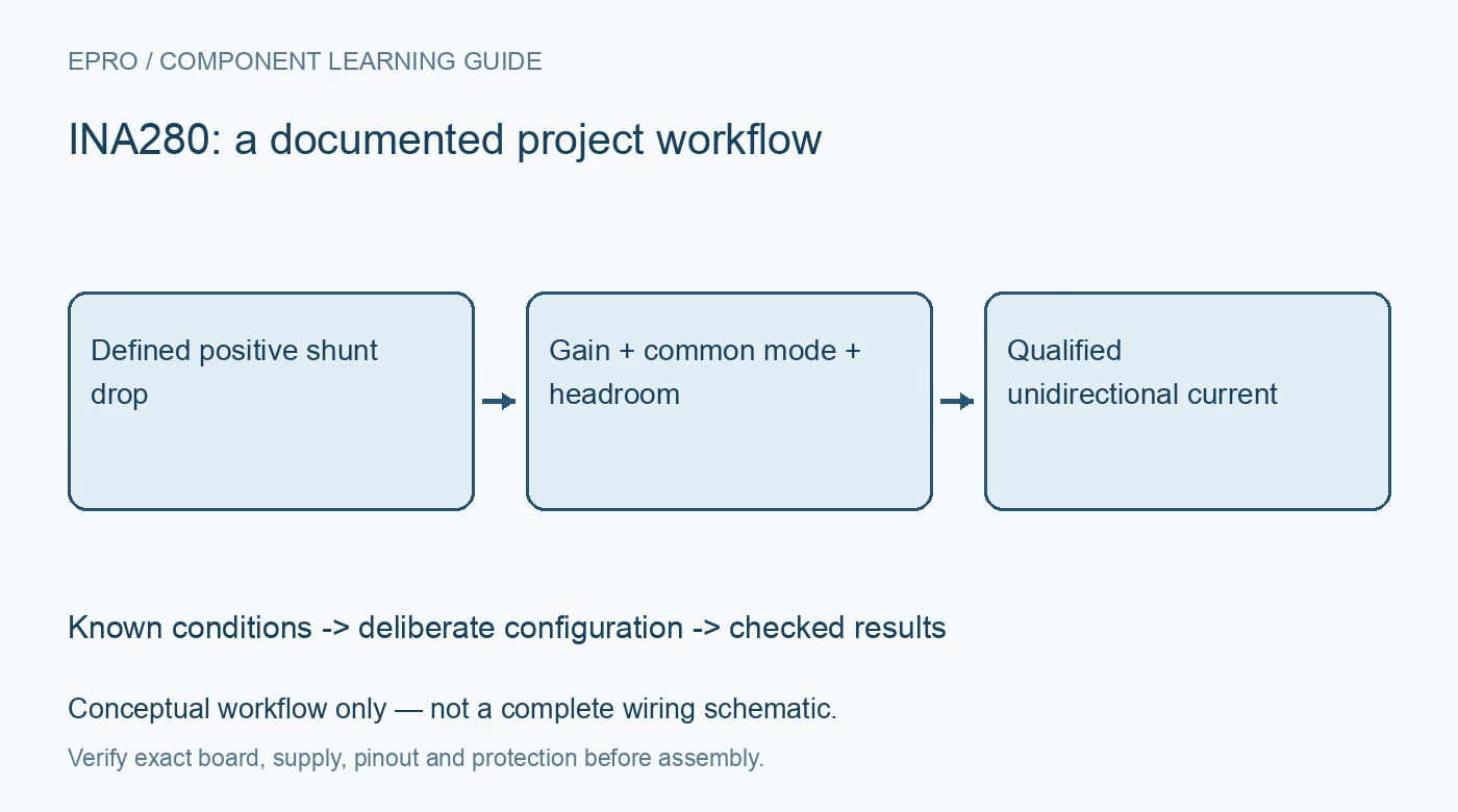
Review INA280 positive common-mode limits, fixed gain, shunt errors, output headroom and recovery from reverse-current overload. This is a documentation-based planning guide, not a report of independent hands-on testing.
1. Confirm unidirectional sensing and gain suffix
INA280 is a unidirectional analog current-sense amplifier, not a bidirectional digital monitor. The fixed-gain options range from 20 V/V through 500 V/V according to the exact suffix. Check the purchased marking, package and pinout before converting output voltage into current. There is no configurable reference pin for shifting the zero-current baseline. A firmware gain constant copied from another suffix produces a systematic error even when the observed output is stable and plausible. Manufacturer documentation.
2. Separate the high-side bus from the supply rail
The operational input common-mode range is 2.7 V to 120 V, while the amplifier supply is independently specified from 2.7 V to 20 V. This allows appropriate high-side measurement without powering the IC directly from the high-voltage bus. It does not permit zero-volt low-side sensing outside the common-mode range. The survival limits are different from operating limits. Treat high bus voltage as a system hazard and use suitable protection and laboratory procedures. Manufacturer documentation.
3. Choose the shunt from both loss and signal range
The ideal positive output is gain multiplied by the shunt differential voltage, with shunt voltage equal to current times resistance. Increasing shunt resistance improves the signal relative to offset but raises power loss and voltage drop. Check current-squared resistance dissipation, pulse ratings, temperature coefficient and connection geometry. Use Kelvin sensing at the resistor terminals so load-current copper does not become an uncontrolled additional shunt. The component value alone does not define assembled resistance accuracy. Manufacturer documentation.
4. Respect both upper and lower output limits
The output cannot reproduce an unlimited voltage up to and beyond its supply rails. Use the applicable swing specifications and receiver input limits to choose gain and shunt resistance. Near zero current, lower output swing and input offset can dominate the measurement. A clipped low output is not evidence of exact zero current, just as a saturated high output is not a valid full-scale measurement. Preserve out-of-range states instead of silently converting them into plausible amperes. Manufacturer documentation.
Newest in the store


5. Build an error budget at the smallest useful current
The specified maximum offset is significant when the shunt signal is only a small number of microvolts. Include gain error, offset drift, shunt tolerance and drift, ADC error and common-mode rejection under the actual operating conditions. Compare absolute errors before expressing a percentage at low current. A gain calibration at one operating point does not remove all offset and temperature effects. State any calculated estimate as a budget, not as an observed accuracy result. Manufacturer documentation.
6. Allow recovery after a negative differential input
The manufacturer describes negative shunt differential voltage as an overload condition for this unidirectional device. Recovery takes time after the input becomes positive again, and the behavior depends on overload conditions. Do not treat a brief reverse-current event as a valid signed measurement or assume immediate recovery from it. If reverse current is normal, select an appropriate architecture. Test expected transients safely and retain invalid-data intervals until the signal path has demonstrably returned to its usable range. Manufacturer documentation.
7. Qualify bandwidth with the actual filter and ADC
The headline 1.1 MHz bandwidth applies to a specified gain condition and does not establish every suffix’s complete system bandwidth. External filtering, ADC acquisition and output loading alter the response. Apply known positive currents within the common-mode and thermal envelope, then inspect step response and any switching-related artifacts. Record gain suffix, shunt value, supply, bus voltage and sampling delay. This produces traceable current records without claiming isolation, negative-current capability or unmeasured dynamic precision. Manufacturer documentation.
Related reading: INA293 Current Amplifier: 7 Checks for Pinouts and Zero-Current Limits.
Catalog note: The exact-part search did not return a matching Epro listing during preparation. Check the current catalog; this guide makes no price, availability or included-accessory claim.