


INA293 Current Amplifier: 7 Checks for Pinouts and Zero-Current Limits

INA293 Current Amplifier: 7 Checks for Pinouts and Zero-Current Limits
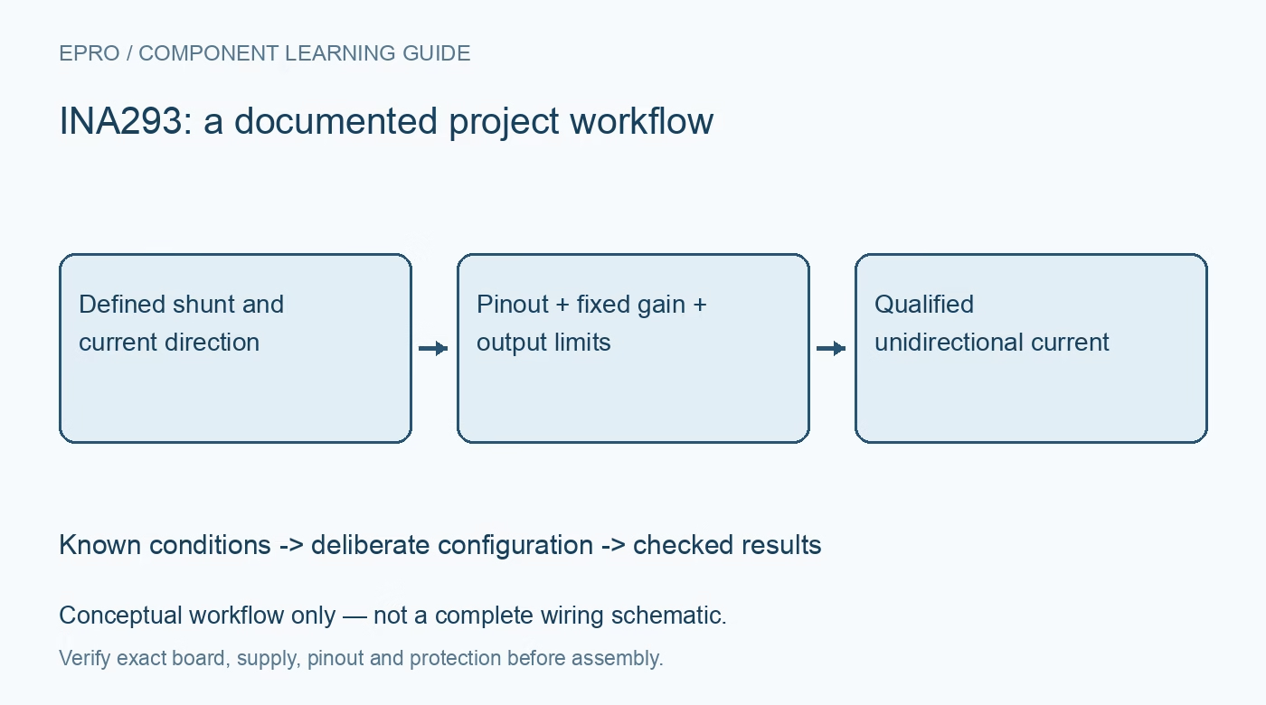
Plan INA293 current sensing with seven checks for A/B pinouts, fixed gain, negative common-mode limits, zero-current behavior and ADC protection. This is a documentation-based planning guide, not a report of independent hands-on testing.
1. Resolve the A/B pinout before choosing a gain
INA293 is not a single interchangeable five-pin footprint. The A and B versions use different supply and sense-input positions, while the final number selects gain. For example, the A supply is pin 5, but the B supply is pin 3. Read the complete order code and the top-view package drawing before routing or connecting a breakout. An apparently identical SOT-23 package is not evidence that a replacement board is wired correctly. Manufacturer documentation.
2. Separate bus common-mode voltage from supply voltage
The operating common-mode range is -4 V to 110 V, whereas the amplifier supply is 2.7 V to 20 V. These are different limits applied to different pins. The wider survival figures are not a valid measurement range. Begin characterization with an isolated, current-limited low-voltage source and a protected load. A high common-mode rating does not provide isolation, make a breadboard suitable for hazardous voltage, or protect a microcontroller from a wiring mistake. Manufacturer documentation.
3. Select fixed gain from the entire current envelope
The available gains are 20, 50, 100, 200 and 500 V/V. Estimate the ideal output as gain multiplied by shunt resistance and current, then leave room for output swing, offset, tolerances and transient current. With a 10-milliohm shunt, gain 50 and 2 A, the ideal output is 1 V and shunt dissipation is 40 mW. These are planning calculations, not measured performance or permission to ignore pulse and thermal ratings. Manufacturer documentation.
4. Do not confuse negative common mode with bidirectional sensing
INA293 is a unidirectional amplifier without a reference-offset input for centering positive and negative current. The ability to operate when both sense inputs sit below ground does not mean it produces a signed output for reversed shunt polarity. Keep the expected measurement direction explicit in the schematic and firmware. If the application needs charging and discharging measurements, select a suitable bidirectional architecture instead of inferring reverse current from a near-zero clipped output. Manufacturer documentation.
Newest in the store


5. Budget the low-current region explicitly
The datasheet identifies a maximum zero-current output of ground plus 20 mV and recommends at least 20 mV divided by gain of differential input to remain in the output linear region. At gain 50 with a 10-milliohm shunt, that boundary corresponds to 40 mA. This is not a universal resolution or accuracy specification. Treat offset, noise, output floor and ADC uncertainty separately, and label readings below the validated operating region rather than reporting false precision. Manufacturer documentation.
6. Preserve the signal path through layout and acquisition
Use Kelvin connections to the shunt, short matched sense routes and local supply bypassing. Adding resistors to change the internally fixed gain is not recommended because internal absolute resistor values vary. Any input filtering must be analyzed for gain error and transient response rather than copied blindly. The advertised 1.3-MHz bandwidth also does not establish the bandwidth of the complete measurement: shunt inductance, filters, ADC loading and sampling timing all contribute. Manufacturer documentation.
7. Validate gain, recovery and host protection together
Record exact suffix, gain, supply, shunt value and temperature conditions with each test set. Compare several known positive currents against a reference instrument, including values near the intended lower bound and maximum operating current. Check settling after steps without deliberately exceeding electrical limits. An amplifier powered above the ADC rail can overdrive its input, so provide a reviewed interface and protection. Publish only the current range supported by these checks; documentation alone is not a calibration certificate. Manufacturer documentation.
Related reading: INA290 Current Amplifier: 7 Checks for Gain and Common-Mode Limits.
Catalog note: The exact-part search did not return a matching Epro listing during preparation. Check the current catalog; this guide makes no price, availability or included-accessory claim.