


TPS22968 Dual Load Switch: 7 Checks for Shared Bias and Rail Sequencing

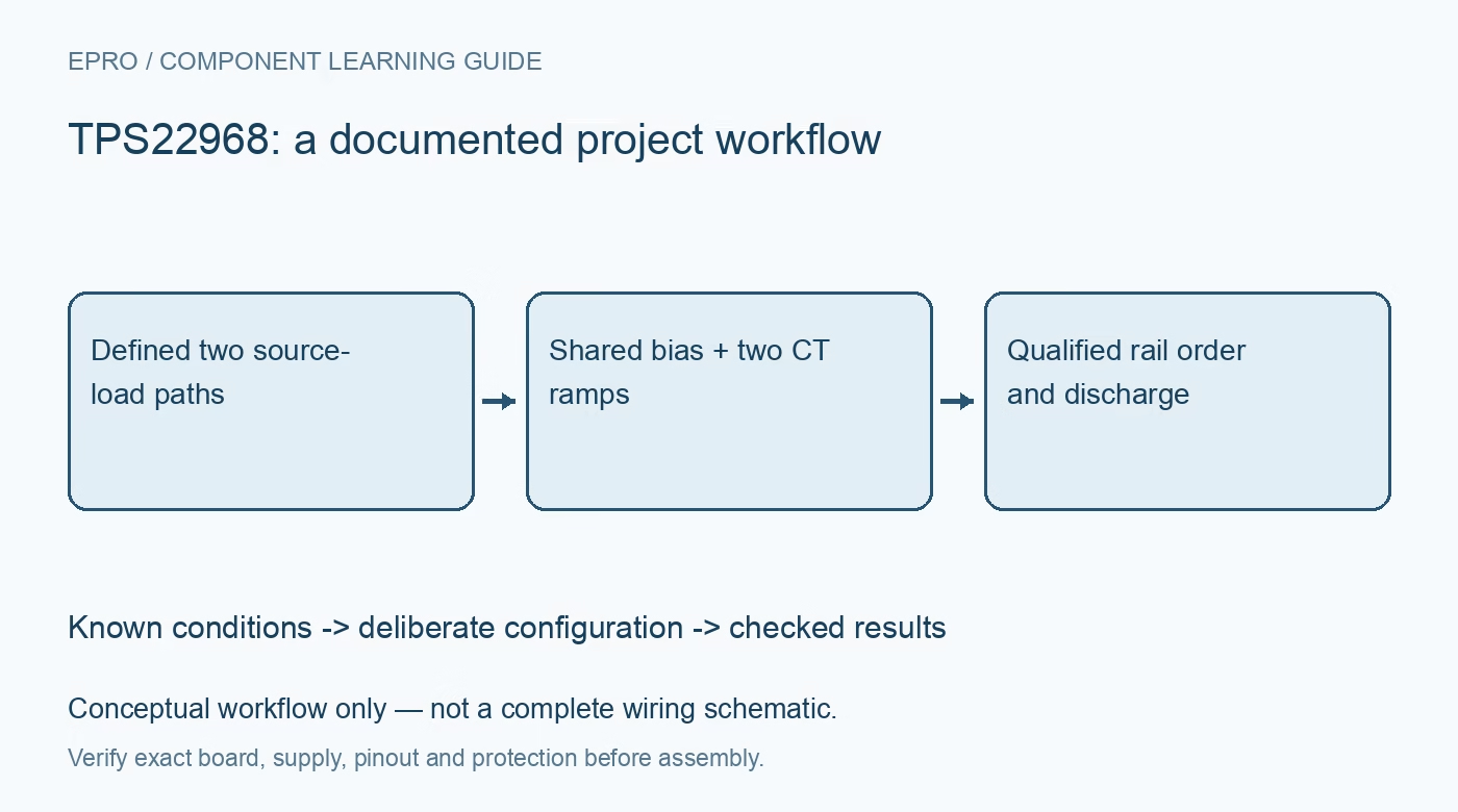
TPS22968 Dual Load Switch: 7 Checks for Shared Bias and Rail Sequencing
Plan TPS22968 dual-rail control with shared VBIAS, individual CT timing, output discharge, reverse paths and total thermal load. This is a documentation-based planning guide, not a report of independent hands-on testing.
1. Trace two independent paths and one shared bias
TPS22968 integrates two load-switch channels with separate VIN, VOUT, ON and CT connections but a shared VBIAS supply. Match all repeated power pins and the thermal pad to the package drawing. Do not infer channel identity solely from a copied board label or an isolated table entry. Verify connectivity against the full schematic and package orientation. The shared bias arrangement means two apparently separate switched rails still depend on a common internal-control supply. Manufacturer documentation.
2. Keep VBIAS and input-voltage conditions explicit
The recommended VBIAS range is 2.5 V to 5.5 V and the input rails operate from 0.8 V to 5.5 V within documented conditions. For best on-resistance performance, VIN should not exceed VBIAS. The datasheet explains that operation above VBIAS increases resistance rather than providing the same tabulated performance. Check each input independently and respect all voltage limits. A valid low-voltage switched rail does not eliminate the requirement for an adequate bias supply. Manufacturer documentation.
3. Define both ON signals through reset and sequencing
Each channel uses active-high ON control, and neither input should float. Establish deliberate off states before the controller starts and during programming or brownout. If the rails must appear in a particular order, implement that order with explicit control and verification rather than assuming different CT capacitors alone create a reliable sequence. Include bias startup and external paths through the downstream load. A disabled channel can still interact with another rail through the system. Manufacturer documentation.
4. Set CT for each load and the combined source demand
The two CT pins independently program turnon slew. Select each capacitor using the manufacturer timing relationships and the expected load capacitance. Capacitive inrush is approximately capacitance multiplied by output slew rate, with active load demand added. Staggering the controls may reduce aggregate source stress, but it needs measurement. Controlled rise time is not regulated current limiting, and a device that starts drawing strongly partway through the ramp can still collapse the upstream supply. Manufacturer documentation.
Newest in the store


5. Distinguish discharge behavior from reverse blocking
The standard TPS22968 includes quick output discharge through a nominal 270 ohm path when a channel is disabled. The N variant differs, so verify the actual marking rather than treating discharge as software configurable. An externally powered output can load this path. The integrated body diode also matters when output voltage exceeds input voltage during source removal. Review capacitance ratios, supply collapse and system reverse paths; this is not a general-purpose reverse-current-blocking or isolation component. Manufacturer documentation.
6. Budget both channels in the same thermal package
The maximum continuous current headline is 4 A per channel under suitable conditions. Calculate each channel’s conduction loss with the applicable on-resistance, then add both contributions when evaluating package temperature. Typical resistance depends on VIN, VBIAS and temperature. A board supporting one loaded rail does not automatically support two equally loaded rails at the same ambient. Include copper area, thermal-pad connection and simultaneous startup in the acceptance plan rather than assigning two independent thermal budgets. Manufacturer documentation.
7. Validate every supply-order combination that can occur
Capture VBIAS, both inputs, both outputs and both control states during intended startup, turnoff and loss of one source. Use bounded loads and a current-limited bench supply for initial work. Verify discharge times against downstream retention and sequencing needs, and inspect for backfeed during collapse. Save CT values, effective capacitances and load profiles alongside observations. A clean single-channel unloaded ramp does not qualify the dual-rail system or establish behavior when another device powers an output externally. Manufacturer documentation.
Related reading: TPS22967 Load Switch: 7 Checks for VBIAS, Slew Rate and Discharge.
Catalog note: The exact-part search did not return a matching Epro listing during preparation. Check the current catalog; this guide makes no price, availability or included-accessory claim.