


TPS22967 Load Switch: 7 Checks for VBIAS, Slew Rate and Discharge

TPS22967 Load Switch: 7 Checks for VBIAS, Slew Rate and Discharge
Review TPS22967 bias requirements, CT-controlled startup, output discharge, thermal limits and externally powered output risks. This is a documentation-based planning guide, not a report of independent hands-on testing.
1. Identify the switched rail and separate bias rail
TPS22967 is a single-channel N-channel load switch with a separate VBIAS supply. Treat VIN, VBIAS and ON as different functions when reviewing a breakout or PCB. Trace both VIN pins and both VOUT pins, and connect the thermal pad as directed by the package guidance. The existence of a bias pin is not optional documentation detail: incorrect biasing can change switching behavior even when the load rail itself appears reasonable. Manufacturer documentation.
2. Apply the recommended VIN-to-VBIAS relationship
The recommended bias range is 2.5 V to 5.5 V, while VIN is specified from 0.8 V up to VBIAS. A low-voltage load rail therefore does not imply the driver can operate from that same low voltage without an adequate bias supply. Review startup and shutdown sequencing for both rails. Use the electrical table corresponding to the actual VBIAS when estimating resistance and timing; a five-volt characterization is not universal behavior. Manufacturer documentation.
3. Define ON during reset and supply changes
ON is active high and must not float. Compare its guaranteed high and low thresholds with the controlling logic, including the source of any pull-up. A controller that starts later than the power rail needs a deliberate safe default. Verify whether signals can back-power other circuitry through board-level connections. Document the intended off state during programming, brownout and cable insertion rather than assuming that firmware will always execute before the load receives energy. Manufacturer documentation.
4. Select CT from startup requirements, not appearance
The CT pin controls output rise time and may be left floating for the documented default behavior. Use the manufacturer timing relationships and applicable operating conditions to choose a capacitor. Estimate capacitive-load inrush from load capacitance multiplied by output slew rate, then include active load demand. Controlled rise time is not the same as regulated current limiting. A load that draws heavily before its input reaches operating voltage can still disturb the upstream supply. Manufacturer documentation.
Newest in the store


5. Distinguish the current rating from thermal capability
The device supports a maximum continuous switch current of 4 A under suitable conditions. Check conduction loss using current squared times the relevant on-resistance, and include PCB copper, ambient temperature and package thermal behavior. The typical 22 milliohm figure is associated with stated bias and input conditions. A small board may not reproduce the datasheet thermal environment. Monitor voltage drop and temperature during a controlled load ramp before assigning a continuous system rating. Manufacturer documentation.
6. Evaluate the quick-output-discharge path
TPS22967 includes a nominal 225 ohm output pulldown when switched off. That helps discharge a capacitive load but also matters if another source drives VOUT. Model the discharge time and the resistor-path dissipation for the actual voltage and capacitance. Do not infer disabled reverse-current blocking from a different load-switch guide. Review this device’s reverse-voltage behavior and the full system power paths before connecting an externally powered peripheral or tying output rails together. Manufacturer documentation.
7. Record startup, turnoff and abnormal supply order
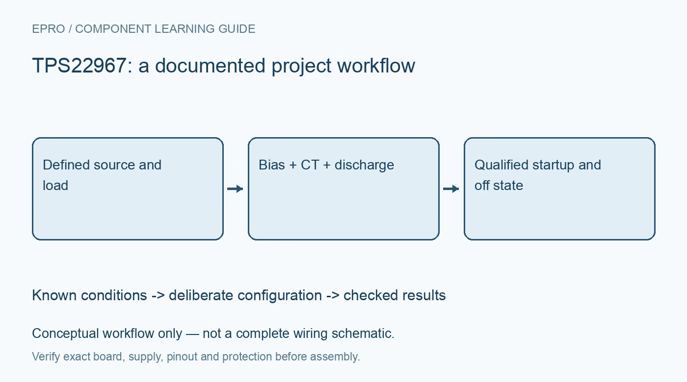
Measure VIN, VBIAS, ON and VOUT together during startup, disable and loss of either supply. Use a current-limited source and representative load capacitance. Check whether output discharge is compatible with required data retention and downstream sequencing. Save CT value, capacitor tolerances, load profile and thermal observations with the waveforms. A conceptual workflow is not a complete power schematic, and a clean unloaded ramp does not establish performance at the intended load. Manufacturer documentation.
Related reading: TPS22964C Load Switch: 7 Checks for Disabled Reverse Blocking and Discharge.
Catalog note: The exact-part search did not return a matching Epro listing during preparation. Check the current catalog; this guide makes no price, availability or included-accessory claim.