


THVD1451 RS-485 Transceiver: 7 Checks for Full-Duplex Links

THVD1451 RS-485 Transceiver: 7 Checks for Full-Duplex Links
Design THVD1451 full-duplex links around separate transmit and receive pairs, fixed enables, termination and logic compatibility. This is a documentation-based planning guide, not a report of independent hands-on testing.
1. Recognize the always-enabled full-duplex architecture
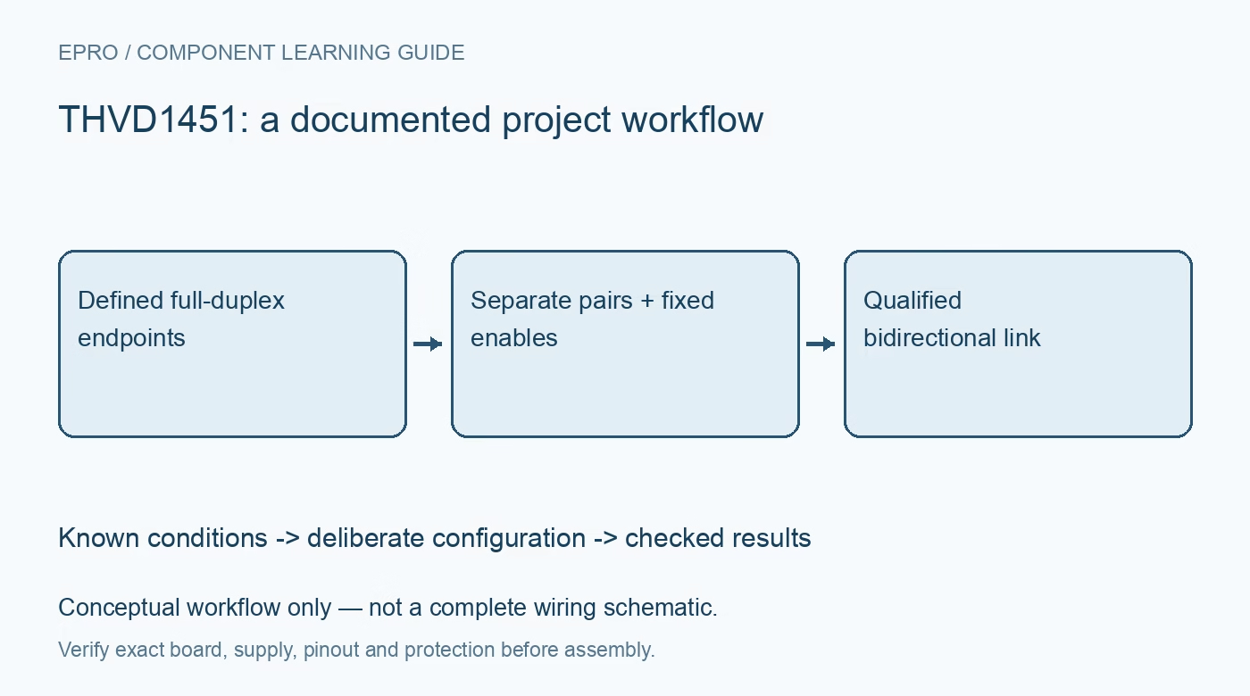
THVD1451 is a full-duplex transceiver with separate transmit and receive differential connections. It does not expose the driver-enable and receiver-enable controls found on many half-duplex devices. That distinction affects both the wiring diagram and the network architecture. Do not copy a two-wire multidriver bus circuit and expect firmware to release this driver through a missing DE pin. Define the endpoint roles and ownership of each driven pair before selecting connectors or writing a communication protocol. Manufacturer documentation.
2. Map transmitter and receiver pairs independently
In the documented eight-pin mapping, Y and Z are transmitter outputs, while A and B are receiver inputs. D is the logic transmit input and R is the logic receive output. Draw the signal flow from one endpoint transmitter to the other endpoint receiver, including polarity. Treat cable labels and third-party A/B conventions cautiously because labeling practices vary. Verify the actual differential truth table at both ends instead of relying solely on matching letters printed beside screw terminals. Manufacturer documentation.
3. Check the 3 V to 5.5 V supply and logic levels
The recommended supply range spans 3 V to 5.5 V. This differs from related transceivers that require a five-volt rail, so verify the exact part instead of transferring family assumptions. Check D input thresholds and R output limits against the controller at the selected supply. A transceiver powered from five volts does not automatically provide a receive signal safe for every lower-voltage microcontroller. Include supply tolerance, controller power-off behavior and local bypassing in the interface review. Manufacturer documentation.
4. Terminate each physical transmission line correctly
Full duplex introduces two signal paths whose cable ends and driven directions must be considered separately. Select termination from the cable impedance and actual topology, not from a habit of placing identical resistor networks at every connector. Keep branches short relative to edge travel time and provide a suitable reference connection. The device headline speed does not eliminate reflections or ground-reference requirements. A point-to-point link is a different termination problem from a multidrop return path with several active drivers. Manufacturer documentation.
Newest in the store


5. Treat 50 Mbps as a conditional capability
The maximum signaling rate is not a promise for an arbitrary cable, connector and node arrangement. Budget driver timing, receiver timing, cable delay and the controller sampling point. Use the datasheet loading conditions when interpreting switching specifications. If the application sends slower serial data, the electrical edge can still be fast enough to reveal poor routing. Establish a link error criterion and cable configuration instead of assuming a successful short bench message proves the installation margin. Manufacturer documentation.
6. Separate common-mode tolerance from isolation and protection
The recommended bus common-mode range and specified ESD robustness describe particular device capabilities. Neither feature provides galvanic isolation or guarantees survival against every industrial surge. Evaluate ground differences, cable exposure, connector discharge and transient protection as a system. The family receiver-loading capability is also a DC loading model, not a guaranteed practical node count at maximum speed. Include termination and cable capacitance before estimating the number of receivers that a particular link can support reliably. Manufacturer documentation.
7. Test both directions without inventing bus-release controls
Use independent patterns in both directions and verify that receive processing handles simultaneous traffic. Exercise an open cable, reversed differential connection and endpoint reset in a controlled low-energy setup. Where multiple transmitters could connect to one pair, redesign ownership rather than looking for an undocumented enable command. Record topology and electrical conditions with the results. This guide contains no measured bit-error performance; a qualified installation requires observations from the actual cable, protection network and controller implementation. Manufacturer documentation.
Related reading: THVD1550 RS-485 Transceiver: 7 Checks for 50Mbps Timing and Loading.
Catalog note: The exact-part search did not return a matching Epro listing during preparation. Check the current catalog; this guide makes no price, availability or included-accessory claim.