


TMUX1109 Multiplexer: 7 Checks for Paired Analog Channels

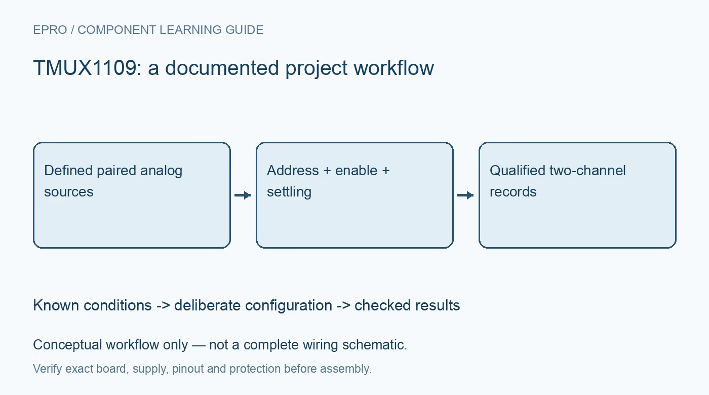
TMUX1109 Multiplexer: 7 Checks for Paired Analog Channels
Plan TMUX1109 paired-channel selection with supply-bounded signals, active-high enable, leakage error and settling time. This is a documentation-based planning guide, not a report of independent hands-on testing.
1. Define the two switched paths and shared address
TMUX1109 provides two four-to-one analog paths that can handle paired single-ended signals or a differential signal arrangement. The same address selection controls both paths; it is not two arbitrarily addressed independent multiplexers. Label each source pair and its corresponding drain connection in the acquisition record. Decide whether the measurement represents a differential pair or two separate quantities before routing. A correct numeric sample is not useful if its companion signal came from a different intended source. Manufacturer documentation.
2. Bound every analog pin by the actual supply rails
The valid analog signal range extends from VSS to VDD. A single-supply circuit with VSS grounded therefore does not accept a genuinely negative input simply because the device also supports dual supplies. Check normal signals, startup transients and disconnected sensor behavior against the chosen rails. The single-supply range begins at 1.08 V, but useful signal headroom still depends on that selected supply. Verify recommended conditions rather than treating absolute-maximum stress values as operating targets. Manufacturer documentation.
3. Use active-high enable and a verified address map
EN low disconnects the paths, while EN high permits the address inputs to select the corresponding switches. This polarity matters when adapting code from another multiplexer family. Derive the address-to-source mapping from the pin-function and logic tables, then confirm it with distinguishable safe input levels. Set a defined enable state during controller reset. Do not leave a floating address or assume an analog switch powers up with the same selected channel as the previous software session. Manufacturer documentation.
4. Keep fail-safe control logic separate from analog protection
Fail-safe logic applies to the control inputs and allows supported control voltages even when the multiplexer supply is absent. It does not make the analog source and drain pins power-off-protected signal inputs. Consider which sensor rails may remain powered when VDD or VSS collapses. Check the resulting pin voltages and current paths explicitly. If a powered sensor can overdrive an unpowered switch, choose suitable sequencing or protection instead of interpreting the control-input feature as universal terminal tolerance. Manufacturer documentation.
Newest in the store


5. Budget leakage against source impedance and temperature
The low typical leakage specification is valuable for high-impedance measurements, but it is not the complete error budget at every temperature and signal voltage. Include the specified limits, PCB contamination, connector insulation and the downstream amplifier or converter input. Leakage multiplied by source impedance can become a visible offset even when switch resistance seems negligible. Define an allowable voltage error first, then decide whether buffering, guarding or a different acquisition impedance is needed for the final board. Manufacturer documentation.
6. Allow settling after the paired switches change state
Break-before-make operation prevents the normal address transition from intentionally joining two sources together, but it does not guarantee that the downstream node is immediately accurate. Charge injection, source impedance, switch resistance and load capacitance all affect recovery. For an ADC, include acquisition kickback and the time available before conversion. Start with large safe differences between selected sources and examine the resulting settling behavior. Discard or flag early samples until the required accuracy has actually been demonstrated. Manufacturer documentation.
7. Preserve pair identity and invalid acquisition states
Store address, enable state, settling qualification and timestamp with the two acquired values. Exercise all four selections, EN low and controller restart, including a case where one sensor is disconnected. Check that stale values cannot be relabeled as a newly selected pair. This is a documentation-based workflow rather than a report of measured leakage or conversion accuracy. Compare the design with a related single-path guide only after accounting for the shared-address paired-path architecture of this device. Manufacturer documentation.
Related reading: TMUX1108 Precision Multiplexer: 7 Checks for Bipolar Signals and Settling.
Catalog note: The exact-part search did not return a matching Epro listing during preparation. Check the current catalog; this guide makes no price, availability or included-accessory claim.