


TPS62825 Buck Converter: 7 Checks for a Real 2 A Rail

TPS62825 Buck Converter: 7 Checks for a Real 2 A Rail
Check TPS62825 two-ampere rail design through exact variant choice, LC selection, light-load operation and dropout conditions. This is a documentation-based planning guide, not a report of independent hands-on testing.
1. Select the two-ampere part and complete ordering code
TPS62825 is the two-ampere member of its converter family; do not transfer a neighboring part current rating into the bill of materials. The suffix also matters. The standard device uses automatic power-save behavior at light load, while the A variant uses forced PWM, and fixed-output variants require the corresponding connection scheme. Confirm the exact orderable code before choosing a divider or expecting a specific standby waveform. Similar package markings do not establish identical operating modes. Manufacturer documentation.
2. Keep input and requested output within the buck envelope
The recommended input range is 2.4 V to 5.5 V, with adjustable output capability from 0.6 V to 4 V for the applicable version. This is a step-down converter, not a boost source when input voltage falls below the required rail. At high duty cycle, conduction losses and load current still affect the attainable output. Define the lowest source voltage at the board, including cable drop and battery discharge, before promising a regulated output throughout the operating cycle. Manufacturer documentation.
3. Choose the inductor and capacitors from documented combinations
Use the manufacturer LC selection guidance rather than selecting components solely from a convenient nominal switching frequency. Check inductor saturation and RMS ratings against ripple and transient current, plus effective capacitor values at their actual DC bias. Output capacitance and inductor choice affect control behavior as well as ripple. Keep the selected component characteristics with the schematic so substitutions are reviewed electrically. A visually similar inductor with a smaller saturation rating can change the converter behavior during a load step. Manufacturer documentation.
4. Budget light-load behavior for the powered instrument
Automatic power-save operation improves light-load efficiency but changes the switching pattern. The nominal 2.2 MHz operating description should not be interpreted as a fixed-frequency promise at every load on the standard device. If the rail powers an ADC, radio or other sensitive circuit, evaluate the resulting ripple spectrum and time-domain behavior in its low-current state. Decide whether the standard or forced-PWM variant fits that requirement. Do not assume software can select a mode pin that the chosen part does not provide. Manufacturer documentation.
Newest in the store


5. Distinguish output capability from thermal and fault margins
Two amperes is not an unconditional current available from any layout at every input and output combination. Estimate conversion losses and evaluate thermal behavior with the intended ambient and board copper. Review the current-limit and protection descriptions separately from the normal load rating. They do not replace checking the upstream source, connectors and load fault energy. Include the peak of a transient demand rather than relying only on the average current reported by a slow meter. Manufacturer documentation.
6. Give enable and power-good signals useful meanings
Define EN during controller reset and source brownout so that the rail does not start unexpectedly. Follow the PG output interface and threshold requirements when choosing a pullup and downstream logic. Power good indicates the regulator-defined output condition; it does not establish low ripple or a completed peripheral initialization. Account for startup time and discharge behavior before permitting sensitive loads to communicate. Where rapid power cycling matters, check residual output voltage instead of assuming an off command immediately creates a fully discharged rail. Manufacturer documentation.
7. Validate the assembled power loop and load transitions
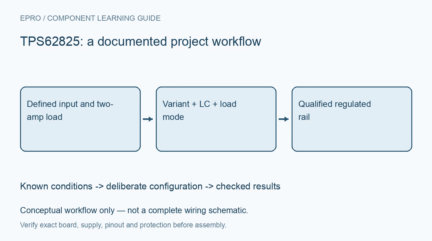
Place the input capacitor, switching loop, inductor and feedback connections according to the layout guidance. Qualify startup and light-to-heavy load transitions with a current-limited source, using short measurement connections that do not exaggerate switching spikes. Repeat at the lowest intended input and the relevant operating temperature. These steps describe a documentation-based validation plan, not measured efficiency or ripple from an Epro board. Keep the exact variant, LC parts and observed operating modes with the final rail qualification record. Manufacturer documentation.
Related reading: TPS62826 Buck Converter: 7 Checks for 3A Rails and Variant Selection.
Catalog note: The exact-part search did not return a matching Epro listing during preparation. Check the current catalog; this guide makes no price, availability or included-accessory claim.