


INA254 Current Monitor: 7 Checks for Its Integrated Shunt

INA254 Current Monitor: 7 Checks for Its Integrated Shunt
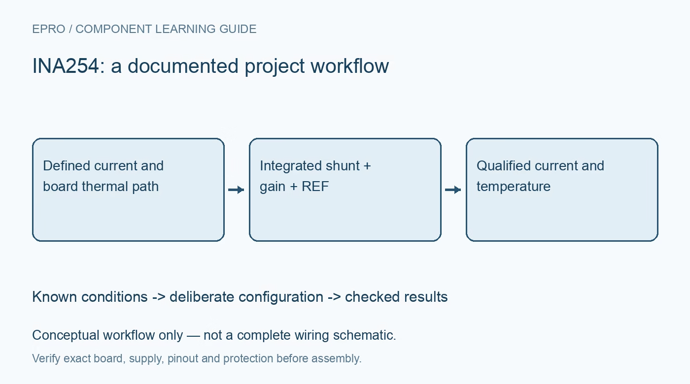
Plan INA254 current sensing with the 400 microohm shunt, exact gain, reference connections and total package heating. This is a documentation-based planning guide, not a report of independent hands-on testing.
1. Use the calibrated integrated-shunt system correctly
INA254 combines its amplifier with a 400-microohm sensing resistor. The system gain specification depends on using those elements together, not treating the accessible shunt as a separately precision-calibrated resistor. Do not add an external shunt value to the current-to-output conversion by habit. Identify the exact gain variant and use its documented overall transfer relationship. Compared with a related integrated-shunt device, both the sensing resistance and output sensitivity can differ substantially despite a familiar functional block diagram. Manufacturer documentation.
2. Distinguish sensing resistance from total package resistance
The complete current path through the package is approximately one milliohm, although only 400 microohms is the Kelvin-sensed element. Thermal calculations therefore need the total package resistance rather than the smaller sensing value alone. Package dissipation scales with current squared, making this distinction important at high current. Treat the simplified calculation as an estimate and apply the manufacturer thermal guidance. A small sensed voltage is not evidence that little heat is being generated in the entire current path. Manufacturer documentation.
3. Apply continuous-current ratings with their board conditions
Headline continuous current capability includes specified ambient and thermal conditions. The documentation discusses copper weight, plane area, airflow and temperature derating; it does not guarantee the same current through an arbitrary breakout or narrow trace. Check the complete path, including connectors and solder joints, before selecting a load. Establish a safe operating envelope for the actual assembly rather than using thermal shutdown as a test limit. Verify the intended sustained current at the highest relevant ambient, not only during a brief room-temperature pulse. Manufacturer documentation.
4. Map power, Kelvin and reserved connections exactly
The package has dedicated IS+ and IS− load-current connections and separate shunt-sense connections. Follow the pin-function table for the intended current direction, sense routing and amplifier inputs. Ground the reserved RES pin as documented and leave DNC terminals unconnected; do not interpret every unused-looking pin as ground. Review all current-carrying terminals and the package power-pad connections together. A generic amplifier footprint or a single thin connection to one current pin does not implement the specified integrated-shunt current path. Manufacturer documentation.
Newest in the store


5. Choose gain and reference for the full signed range
The available sensitivities are 20, 40 and 75 mV per ampere, depending on variant. Set REF1 and REF2 according to the documented reference configurations, including the intended zero-current level and direction. Calculate output endpoints at the largest positive and negative currents, then compare them with amplifier swing and ADC input limits. A centered reference is useful only if both current directions fit. Include reference error, output loading and supply tolerance rather than assuming that bidirectional capability guarantees a symmetric usable measurement range. Manufacturer documentation.
6. Check supply and bus voltage as separate limits
The amplifier supply is 2.7 V to 5.5 V, while the supported bus common-mode range is −4 V to 80 V under recommended conditions. The wider bus range does not make the logic-side output an isolated signal or permit arbitrary transients. Evaluate bus disturbances, source sequencing and controller power-off behavior independently. Protection for a high-energy installation remains a system design responsibility. Validate the low-energy signal chain first and avoid assuming that a high common-mode rating makes exposed high-current wiring safe. Manufacturer documentation.
7. Qualify current accuracy alongside temperature rise
Begin with known low currents to verify zero level, polarity and scaling, then increase load only within the assembly thermal plan. Compare the current record with an appropriate reference and record temperature and settling time. Preserve calibration conditions and measurement uncertainty rather than presenting one matching value as proof over the full range. This guide provides no independent current or thermal measurements. A reproducible record includes exact gain variant, reference wiring, copper construction, airflow and the evidence supporting the accepted continuous-current envelope. Manufacturer documentation.
Related reading: INA253 Integrated-Shunt Monitor: 7 Checks for References and Thermal Limits.
Catalog note: The exact-part search did not return a matching Epro listing during preparation. Check the current catalog; this guide makes no price, availability or included-accessory claim.