


INA250 Current Monitor: 7 Checks for Gain and Package Heating

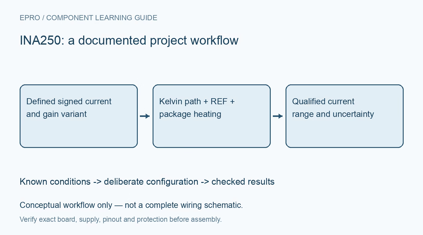
INA250 Current Monitor: 7 Checks for Gain and Package Heating
Plan INA250 integrated-shunt sensing with exact gain selection, the separate package resistance, reference limits and thermal derating. This is a documentation-based planning guide, not a report of independent hands-on testing.
1. Select the exact current-to-voltage gain variant
INA250 combines its amplifier with an integrated two-milliohm shunt and offers four output sensitivities: 200, 500 and 800 millivolts per ampere, plus two volts per ampere. Identify the full A1 through A4 variant before calculating a current from output voltage. These sensitivities already represent the system relationship; do not multiply by another external shunt value. A gain that resolves small currents well may run out of output headroom long before the package reaches its thermal current capability. Manufacturer documentation.
2. Use the matched amplifier and Kelvin shunt together
The specified system performance depends on the integrated shunt and amplifier functioning as the matched measurement system. Accessible shunt-sense terminals do not make the resistor alone equivalent to that calibrated combination. Follow the SH+ and SH− connections to the corresponding amplifier inputs when no filtering is needed, or use the documented filter arrangement. Route the high-current terminals according to the package guidance. A visually short but incorrectly shared sense connection can reintroduce the voltage-drop errors that the Kelvin structure is intended to avoid. Manufacturer documentation.
3. Calculate heat from the complete current path
Although the sensed resistor is two milliohms, the total package resistance is approximately 4.5 milliohms. Use the total path when estimating dissipation rather than assuming every ampere heats only the precision sensing element. The current-squared relationship makes the difference important as the load increases. Include terminals, copper and connectors in the installation review. A low shunt voltage is a measurement characteristic, not proof that the assembled current path has negligible power loss or an acceptable steady-state temperature. Manufacturer documentation.
4. Apply current derating to the actual board
The documentation describes fifteen-ampere operation through 85 degrees Celsius under stated board conditions, with derating to ten amperes at 125 degrees Celsius in the specified no-airflow case. Copper weight, area and airflow change thermal performance. Those conditions cannot be silently transferred to a narrow adapter or a different connector. Define a continuous-current envelope for the real assembly and inspect its sustained temperature. A brief pulse that produces a plausible voltage reading does not establish safe continuous operation at the same current. Manufacturer documentation.
Newest in the store


5. Respect the reference limit independently from the supply
The amplifier supply range is 2.7 V to 36 V, but REF is limited to the documented range up to eighteen volts as well as the applicable supply restriction. Do not tie it to an arbitrarily high supply simply because both terminals belong to the same package. Choose the zero-current level and calculate both signed output endpoints with the selected gain. Check amplifier swing, ADC range and reference source capability together so the accepted measurement range is explicit rather than inferred from the word bidirectional. Manufacturer documentation.
6. Keep common-mode capability separate from isolation
The recommended common-mode range extends from approximately negative 0.1 V to 36 V. It does not permit the wider negative bus excursions supported by some other current-monitor families, nor does it provide galvanic isolation. Evaluate input transients, source sequencing and controller power-off conditions against the exact limits. A high-voltage supply capability also does not make the output safe for a lower-voltage ADC. Provide the required signal conditioning and system protection independently before moving from a low-energy evaluation to a high-current installation. Manufacturer documentation.
7. Qualify low-current error and high-current heat separately
Start by checking zero offset, polarity and gain against an appropriate current reference, then extend the range only within the board thermal plan. Record ambient conditions, dwell time and output settling with each comparison. Include reference and ADC uncertainty rather than presenting a single matching point as full-range calibration. This article claims no independent accuracy or temperature measurements. Preserve the exact gain variant, sense connections, reference setting and current-path construction so both the measurement uncertainty and continuous-current limit can be reviewed later. Manufacturer documentation.
Related reading: INA254 Current Monitor: 7 Checks for Its Integrated Shunt.
Catalog note: The exact-part search did not return a matching Epro listing during preparation. Check the current catalog; this guide makes no price, availability or included-accessory claim.