


TPS22971 Load Switch: 7 Checks for Adjustable Startup and PG

TPS22971 Load Switch: 7 Checks for Adjustable Startup and PG
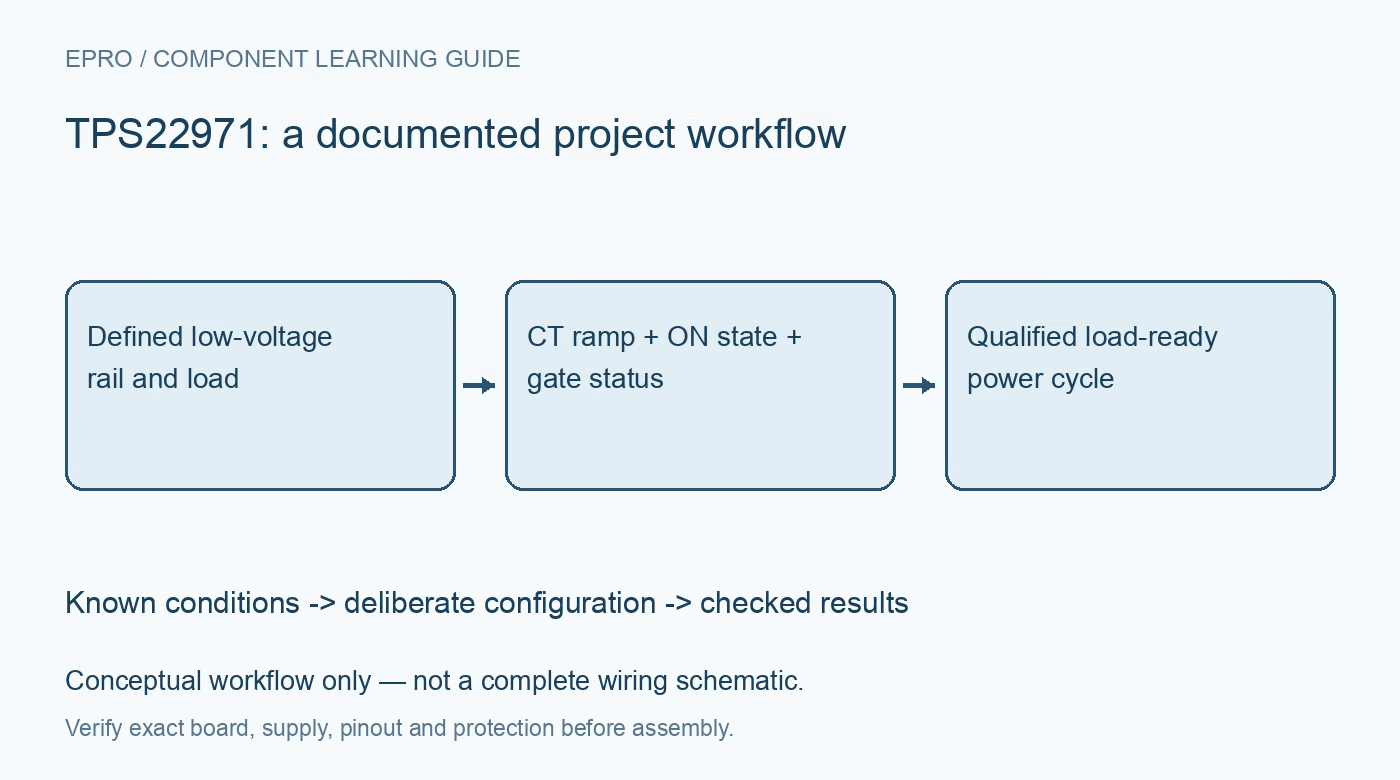
Plan TPS22971 rail startup with a timing capacitor, gate-based power-good meaning, defined ON control and output discharge. This is a documentation-based planning guide, not a report of independent hands-on testing.
1. Establish the voltage and current envelope first
TPS22971 is a three-ampere load switch for input voltages from 0.65 V to 3.6 V under its specified conditions. It is not a general five-volt power switch. Account for source tolerance and transient peaks as well as the steady rail voltage. The low on-resistance is conditional on input voltage and temperature, so use the applicable limits when estimating drop and heating. Review the tiny wafer-level package, board connections and load profile before accepting the headline current for an assembled design. Manufacturer documentation.
2. Define ON during reset because it has no internal bias
The active-high ON input supports low-voltage control under the documented electrical conditions, but it must not be left floating. Choose an external default and check controller startup, shutdown and partial-power behavior. A GPIO driven by firmware after boot cannot guarantee the desired state before configuration. Check the allowable control voltage independently from the switched input. Include the possibility that the controller remains powered while VIN disappears, so the review covers more than the normal state with all rails present. Manufacturer documentation.
3. Calculate the ramp with the actual timing-capacitor rule
A capacitor from CT to ground adjusts the output slew rate, allowing startup time and capacitive inrush to be traded deliberately. Use the documented relationship for VIN and desired slope rather than assuming a universal microseconds-per-picofarad constant. The datasheet gives a special rule for calculated CT values below 220 picofarads when solving the timing equations. Apply that rule instead of extrapolating without qualification. Distinguish total turn-on time, rise time and the power-good interval when building the startup sequence. Manufacturer documentation.
4. Budget inrush together with startup load current
Estimate capacitor charging current from output capacitance and the selected voltage slope, then add whatever the downstream circuit draws while starting. A controlled ramp reduces charging demand but is not a programmable current-limit function. Check source droop and whether the downstream load enters a brownout-restart cycle during the ramp. Include capacitance tolerance and source impedance in the timing review. Select a startup policy that the load can actually tolerate, not only one that produces a small nominal charging-current estimate. Manufacturer documentation.
Newest in the store


5. Interpret PG as pass-FET readiness rather than regulation
The power-good signal indicates that the pass-FET gate is driven high and the switch is fully on. It does not independently regulate or certify a precise downstream output voltage. A weak source can therefore remain a system problem even when the switch has completed its gate transition. PG is an active-high open-drain interface requiring the appropriate external pullup and voltage limits. Use its timing as one qualification condition, and separately check that the load supply meets the load voltage requirement. Manufacturer documentation.
6. Include discharge and thermal recovery in the off state
The disabled switch applies a typical 150-ohm quick-discharge path from VOUT to ground. That path varies with conditions and can load a rail maintained through another supply or signal connection. Review back-power and discharge energy before assuming ON low produces immediate complete power removal. Thermal shutdown is also a protective event rather than a normal current-management strategy. Define whether automatic recovery could restart the load unexpectedly and provide upstream protection appropriate for a short or excessive sustained demand. Manufacturer documentation.
7. Qualify startup permission and a genuine restart
Begin with a current-limited source and representative load capacitance. Observe VIN, VOUT, ON and PG during startup, shutdown and the shortest intended off interval. Confirm that the peripheral actually resets and that its startup demand does not invalidate the selected CT ramp. Repeat at relevant source and load extremes while checking temperature. This is a documentation-based validation plan, not measured Epro-board timing. Preserve the capacitor value, pullup source and accepted load-ready conditions with the final power-sequencing record. Manufacturer documentation.
Related reading: TPS22970 Load Switch: 7 Checks for Low-Voltage Power Cycling.
Catalog note: The exact-part search did not return a matching Epro listing during preparation. Check the current catalog; this guide makes no price, availability or included-accessory claim.