


INA2181 Current Amplifier: 7 Checks for Two Signed Channels

INA2181 Current Amplifier: 7 Checks for Two Signed Channels
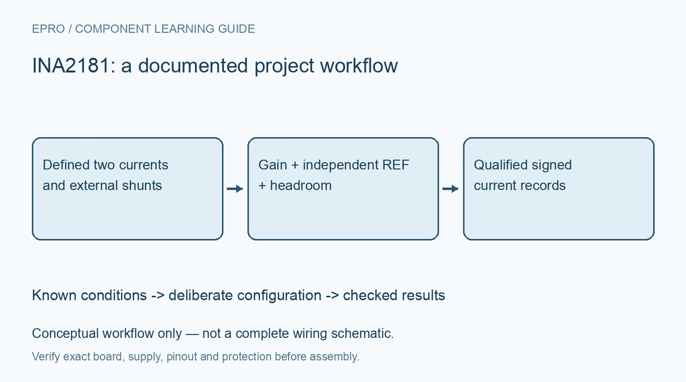
Plan INA2181 dual-channel current sensing with external Kelvin shunts, separate references, gain choice and independent error budgets. This is a documentation-based planning guide, not a report of independent hands-on testing.
1. Identify the dual-channel amplifier and its external shunts
INA2181 contains two current-sense amplifier channels, not two integrated current-carrying shunts. Each channel requires an appropriately chosen external resistor and Kelvin sense connections. The shared family documentation also covers single- and four-channel devices with different packages and pin maps. Verify the exact dual-channel symbol before routing. Define whether the two channels observe separate loads or different points in one system so their current directions, grounds and acceptance criteria are explicit rather than inferred from a generic two-channel diagram. Manufacturer documentation.
2. Choose the fixed gain before selecting the shunt
The available gain options are twenty, fifty, one hundred and two hundred volts per volt. For each channel, calculate the shunt voltage and resulting output excursion at the largest intended positive and negative current. Then check shunt dissipation, pulse rating and measurement resolution. Increasing gain helps small signals but reduces usable headroom. A low resistor value reduces current-path loss while making offset and layout-induced voltage more significant. Select the combination from the required error and thermal budgets instead of maximizing gain or minimizing resistance in isolation. Manufacturer documentation.
3. Set each reference for its actual signed range
REF1 and REF2 establish the zero-current output levels independently within the documented supply-related limits. Choose the reference and calculate both signed output endpoints using the selected gain and shunt. Check output swing and downstream ADC limits rather than assuming a midpoint reference guarantees equal useful range in both directions. Give reference sources suitable impedance and startup behavior. A shared reference can simplify a design but also introduce a common error or transient, so document whether the channels intentionally share that dependency. Manufacturer documentation.
4. Separate amplifier supply from input common mode
The shared amplifier supply operates from 2.7 V to 5.5 V, while the input common-mode capability extends from negative 0.2 V to 26 V under recommended conditions. These are separate limits, not interchangeable terminal ratings. Check power sequencing and possible bus disturbances for each channel. Neither a higher common-mode capability nor a differential input provides galvanic isolation. Include controller power-off and ADC-input behavior so an otherwise valid current measurement cannot back-power a lower-voltage signal chain or violate a receiving pin limit. Manufacturer documentation.
Newest in the store


5. Keep load current out of the Kelvin sense paths
Route separate sense traces to the appropriate shunt terminals rather than measuring across a convenient length of current-carrying copper. Check both channels for polarity and shared return errors. If input filtering is needed, follow the manufacturer arrangement and consider the gain error introduced by external series resistance. Matching components alone does not remove every error caused by source impedance or parasitic coupling. Include the shunt tolerance and temperature coefficient in the measurement budget instead of assigning all uncertainty to the amplifier. Manufacturer documentation.
6. Budget offset and bandwidth per channel and condition
Offset specifications depend on the stated common-mode conditions, so do not apply the smallest headline value across every bus voltage. Include gain error, offset drift, shunt heating, reference error and ADC uncertainty at both low and high current. The bandwidth headline is also gain dependent; a value quoted for the lowest-gain option does not automatically describe another variant. For changing currents, define the required settling interval and filtering. A simultaneous software read of two ADC inputs is not proof that the complete analog paths have identical timing. Manufacturer documentation.
7. Verify two-channel identity and overload recovery separately
Use safe known currents to check zero level, sign and scale on each channel before exercising both together. Include a disconnected sensor path, reference startup and a temporary over-range condition within terminal limits, then verify recovery before accepting new values. Store channel identity and reference configuration with the readings. This documentation-based article claims no independent accuracy or transient measurements. Retain the actual shunt construction, gain variant and calibration evidence so later resistor or ADC changes prompt a deliberate review of both signed measurement channels. Manufacturer documentation.
Related reading: INA181 Current Amplifier: 7 Checks for REF and Shunt Errors.
Catalog note: The exact-part search did not return a matching Epro listing during preparation. Check the current catalog; this guide makes no price, availability or included-accessory claim.