


THVD1552 RS-485 Transceiver: 7 Checks for Full-Duplex Enable Timing

THVD1552 RS-485 Transceiver: 7 Checks for Full-Duplex Enable Timing
Build THVD1552 links with a five-volt rail, independent transmit and receive enables, exact package pins and qualified cable timing. This is a documentation-based planning guide, not a report of independent hands-on testing.
1. Keep the enabled full-duplex architecture explicit
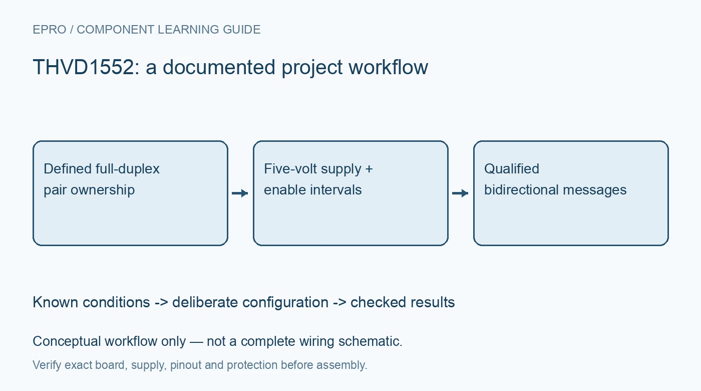
THVD1552 has separate transmit and receive differential pairs, plus independent driver and receiver enable controls. It is different from the always-enabled full-duplex relative and from the half-duplex family members. Identify who drives each physical pair and whether an inactive driver must release it. The presence of enables does not establish a multidriver arbitration protocol. Put the electrical pair ownership and expected simultaneous traffic in the system diagram before writing controller code or copying a generic two-wire RS-485 connection. Manufacturer documentation.
2. Review the selected package pin table
The manufacturer describes different package arrangements, including ten-pin VSSOP and fourteen-pin SOIC implementations. Use the exact table for the selected device rather than the pin numbers of an eight-pin relative. Identify Y and Z as transmit outputs, A and B as receiver inputs, D as logic transmit input and R as receive output. Check all required power and ground terminals. Differential connector labels can vary between vendors, so establish actual polarity through the truth table and a documented endpoint wiring convention. Manufacturer documentation.
3. Qualify the five-volt rail and processor interface
The supply operating range is 4.5 V to 5.5 V, not the broader lower-voltage range supported by some other transceiver families. Check voltage at the package during startup and active traffic, including source tolerance and cable drop. Separately compare transmit and enable input levels with the processor, and receive output levels with processor input limits. A five-volt receiver output is not automatically safe for every lower-voltage controller. Include partial-power behavior and local bypassing in the interface review. Manufacturer documentation.
4. Define independent driver and receiver defaults
DE enables the driver when high, while the receiver-enable input is active low. Build a state table that includes transmit-only, receive-only, simultaneous activity and the required inactive state. Check weak internal biasing and choose external defaults for controller reset as appropriate. When reception is disabled, R can be high impedance, which requires a deliberate receiving-logic state. Do not let firmware assume that a disabled receiver still drives a valid idle serial level merely because its last output value looked reasonable. Manufacturer documentation.
Newest in the store


5. Include enable intervals around the serial message
The driver must become active before the first physical data symbol and remain active until the final symbol finishes. A software transmit-buffer-empty event may occur before that final wire-level transition. Likewise, allow the documented receiver-enable timing before accepting incoming data. Budget the relevant limits and controller scheduling margin rather than only typical propagation delay. Verify the exact events used to change DE and receiver state, particularly when a protocol turns a return path around quickly or a controller handles simultaneous traffic. Manufacturer documentation.
6. Evaluate cable loading and protection as a system
Terminate each differential transmission line according to its impedance, endpoints and driven direction. Keep branches and protection capacitance in the high-speed review rather than assuming the fifty-megabit headline guarantees every cable installation. Extended common-mode operation and strong ESD ratings are defined characteristics, not isolation or universal surge protection. DC receiver-loading figures also do not alone determine a reliable network size. Review ground differences, topology and fault exposure independently before accepting an industrial link design. Manufacturer documentation.
7. Qualify enabled traffic and fault recovery on both pairs
Use different patterns in both directions and inspect first and last symbols under the intended enable sequence. Exercise controller reset, cable removal and endpoint power changes in a safe setup. Confirm ownership if multiple drivers can access a path and retain a response for contention or lost communication. This article contains no independent error-rate or surge-survival measurements. Record cable, supply, termination and enable timing so a later firmware or topology change is compared with a reproducible qualified configuration. Manufacturer documentation.
Related reading: THVD1551 RS-485 Transceiver: 7 Checks for a Five-Volt Full-Duplex Link.
Catalog note: The exact-part search did not return a matching Epro listing during preparation. Check the current catalog; this guide makes no price, availability or included-accessory claim.