


THVD1424 RS-485 Transceiver: 7 Checks for Configurable Duplex Links

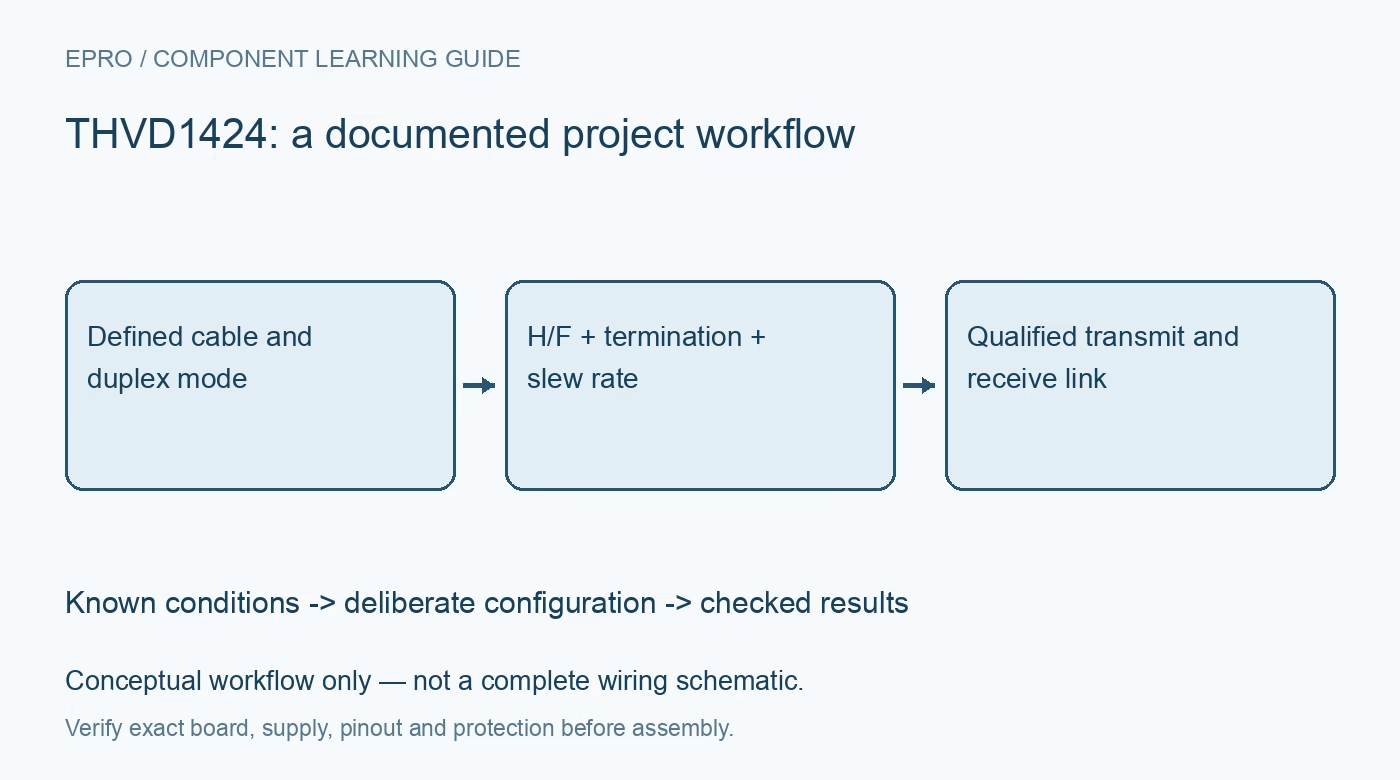
THVD1424 RS-485 Transceiver: 7 Checks for Configurable Duplex Links
Check THVD1424 duplex selection, switchable termination, logic supply and slew-rate control before qualifying an RS-485 link. This is a documentation-based planning guide, not a report of independent hands-on testing.
1. Define the cable topology before configuring pins
The THVD1424 supports selectable half-duplex and full-duplex operation, allowing one device to serve different network arrangements. That flexibility makes the configuration part of the physical wiring design. Draw cable pairs, node positions, direction of communication and intended termination locations. Do not assume a connector that worked in one mode exposes the correct pair in another. Assign configuration defaults explicitly so a controller reset cannot silently change the interpretation of a previously qualified cable connection. Manufacturer documentation.
2. Keep VCC and VIO requirements distinct
The bus-side supply operates from 3 V to 5.5 V, while the logic supply accepts 1.65 V to 5.5 V. Check both rails and their associated input thresholds, decoupling and sequencing guidance. The lower logic range does not make the bus supply interchangeable with a low-voltage microcontroller rail. Review enabled, disabled and unpowered states for every connected controller signal. Document the actual supplies used for timing verification because bus amplitude and digital interface behavior depend on those conditions. Manufacturer documentation.
3. Verify what the H/F selection actually connects
With H/F high, the device operates half duplex and both driver and receiver use Y and Z. With H/F low, it operates full duplex: the driver uses Y and Z while the receiver uses A and B. Treat this as an explicit signal-routing truth table, not just a protocol preference. Confirm polarity on each pair before exchanging packets. Any live mode change also needs the manufacturer switching timing and a system-level plan to avoid contention or interpreting an incomplete transmission. Manufacturer documentation.
4. Enable only the terminations required by the network
The device includes nominal 120-ohm switchable terminations. In full duplex, TERM_TX controls the Y/Z termination and TERM_RX controls A/B. In half duplex, TERM_TX controls the active Y/Z termination and TERM_RX is not the deciding control. Enabling every on-chip termination at every node overloads a multidrop bus. Mark endpoints and required termination separately for each operating mode. Confirm behavior when the device is unpowered, because internal termination is not an unconditional passive resistor permanently across the cable. Manufacturer documentation.
Newest in the store


5. Choose slew rate to fit the real cable
SLR high selects operation up to 500 kbps; low or floating selects the faster mode, specified up to 20 Mbps under its conditions. Explicitly set the desired level even when the documented default seems convenient. Faster edges are not automatically better on a short-data, long-cable network: they can increase reflection and emissions sensitivity. Match timing tables, cable characteristics and receiver margins to the selected mode. A nominal UART rate alone does not qualify the physical waveform or establish electromagnetic compatibility. Manufacturer documentation.
6. Handle enable timing and receive states deliberately
DE high enables the driver and the active-low receiver enable controls whether R drives its logic output. A disabled receiver output is high impedance, not necessarily a valid high or low bit. Allow the required enable and disable delays, and wait for the final physical transmit bit before releasing a half-duplex bus. Open, short and idle failsafe features provide defined behavior in specified cases; they do not replace framing checks, collision prevention or an error-handling policy in the communication protocol. Manufacturer documentation.
7. Qualify the link without overstating protection ratings
Test the chosen duplex mode, termination map, speed and supplies across representative cable and node configurations. Observe differential voltage and common-mode conditions using suitable equipment. Include startup, controller reset and a missing peer in the test plan, with bounded, reviewed fault methods. The documented ESD and bus-fault ratings are conditional device specifications, not galvanic isolation or proof of complete-system surge compliance. Retain configuration levels and observed packet errors so a passing demonstration can be reproduced after firmware or cabling changes. Manufacturer documentation.
Related reading: THVD1552 RS-485 Transceiver: 7 Checks for Full-Duplex Enable Timing.
Catalog note: The exact-part search did not return a matching Epro listing during preparation. Check the current catalog; this guide makes no price, availability or included-accessory claim.