


INA4180 Current Amplifier: 7 Checks for Four Unidirectional Channels

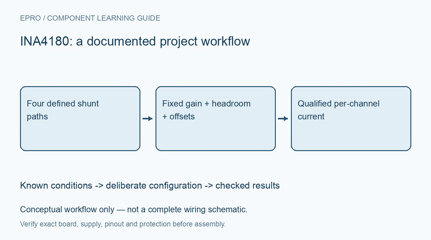
INA4180 Current Amplifier: 7 Checks for Four Unidirectional Channels
Plan INA4180 quad-channel current sensing with external shunts, fixed gain, common-mode limits and channel-specific error checks. This is a documentation-based planning guide, not a report of independent hands-on testing.
1. Define four separate current measurement paths
The INA4180 provides four current-sense amplifier channels in a fourteen-pin TSSOP package. The shunts are external components, so the amplifier alone does not establish current range, power rating or isolation. Draw each positive current direction and assign an output to its corresponding load. Use a channel table containing shunt resistance, expected maximum current and ADC input. A shared package can simplify acquisition hardware, but it does not eliminate the need to qualify each measurement path separately. Manufacturer documentation.
2. Match the fixed-gain suffix to every channel
The family provides gain options of twenty, fifty, one hundred or two hundred volts per volt. Select the complete ordering suffix against the expected shunt drop and ADC headroom. Do not assume gain can be changed by firmware or by adding a casual feedback resistor. For each channel, calculate approximate output from current multiplied by shunt resistance and fixed gain. Keep margins for offset and output swing rather than choosing a range that reaches an ideal supply rail at maximum current. Manufacturer documentation.
3. Separate amplifier supply from bus common mode
The amplifier operates from a 2.7-V to 5.5-V supply, while its specified input common-mode range extends from minus 0.2 V to 26 V. These limits describe different electrical quantities. A high-side bus connection does not authorize connecting the supply pin to that bus. Review transient conditions and all input-pin limits, including disconnected-load states. The part is not galvanically isolated; any controller or measurement equipment connected to its outputs shares the system’s grounding and safety considerations. Manufacturer documentation.
4. Design shunts and Kelvin routing as precision components
Select resistance, power handling, tolerance and temperature coefficient for each current path. Calculate dissipation using current squared times resistance and assess hot shunt error at the real board temperature. Route the two sense inputs from the intended shunt terminals rather than from convenient power traces. Copper drop outside those points otherwise becomes part of the measured voltage. Keep channel identification consistent through connectors and ADC software, because correct electrical gain cannot compensate for an output assigned to the wrong load. Manufacturer documentation.
Newest in the store


5. Do not interpret reverse current as a signed measurement
This ground-referenced architecture does not offer a separate midpoint reference input for measuring both polarities as a signed output. A near-ground output can represent zero current, a small reverse input, limited output swing or an acquisition issue. Define reverse-current behavior as a limitation of the measurement path rather than inventing a negative result from a clipped output. If reverse direction matters, choose a suitable sensing architecture and review protection separately; changing software sign conventions cannot create missing analog range. Manufacturer documentation.
6. Build an error budget for each operating condition
Offset voltage depends on the specified conditions, including input common mode, and its contribution becomes especially important at small shunt drops. Include gain error, shunt tolerance and drift, ADC reference uncertainty and routing effects. Bandwidth also depends on the gain option; a family headline is not a universal response for every suffix. Compare a known zero condition and several bounded forward currents on each channel. Save raw ADC values with calculated current so scale and offset corrections remain auditable. Manufacturer documentation.
7. Check channel independence under simultaneous activity
A quiet single-channel test does not represent a board with four changing loads. Exercise representative combinations while watching shared supply disturbance, ground movement and nearby shunt heating. Check settled response and saturation recovery without exceeding input or shunt ratings. Document channel mapping, gain suffix, source voltage, reference conditions and the observed uncertainty range. The useful deliverable is four qualified current records under known conditions, not a blanket claim that packaging four amplifiers together guarantees identical accuracy in every application. Manufacturer documentation.
Related reading: INA2180 Current Amplifier: 7 Checks for Two Unidirectional Channels.
Catalog note: The exact-part search did not return a matching Epro listing during preparation. Check the current catalog; this guide makes no price, availability or included-accessory claim.