


TPS62868 Buck Converter: 7 Checks for a Four-Amp Core Rail

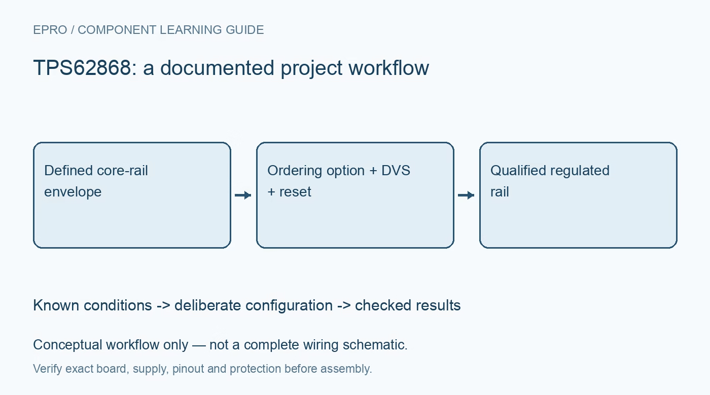
TPS62868 Buck Converter: 7 Checks for a Four-Amp Core Rail
Check TPS62868 ordering options, startup selection, dynamic voltage scaling and reset behavior before powering a programmable core rail. This is a documentation-based planning guide, not a report of independent hands-on testing.
1. Select the four-amp ordering option deliberately
The TPS62868 belongs to a converter family whose datasheet also covers a six-amp device. The TPS62868 entries are rated for four-amp output capability under the specified electrical and thermal conditions. Record the complete orderable number rather than inferring current rating from a shared document title. Input operation spans 2.4 V to 5.5 V. Begin with the processor’s rail limits, load transients and startup permissions so the chosen converter option solves a defined power problem. Manufacturer documentation.
2. Match voltage range and multifunction pin to the board
Ordering options select different output-voltage ranges and step sizes, and provide either VSET/VID or PG functionality. These options cannot be represented by one interchangeable schematic symbol without further annotation. Record the startup value, programmable range, I2C target address and multifunction-pin role together. Verify the complete suffix against the device-options table before assembly. A software command cannot repair a board that expects power-good behavior from a pin fitted as the startup and voltage-selection interface. Manufacturer documentation.
3. Preserve the startup-selection conditions
For selectable variants, the external VSET network determines startup behavior and target-address selection. Use the recommended resistor table and loading guidance, including leakage or capacitance introduced by test equipment and attached logic. Keep EN defined rather than floating. Verify the rail reached immediately after enable before allowing the processor to start, because later I2C programming occurs too late to correct an unsafe initial voltage. Store the actual component value and selected option in the firmware release documentation. Manufacturer documentation.
4. Treat voltage scaling as a system transaction
Different variants support different programmable ranges with corresponding step sizes. Translate a requested voltage using the correct table, clamp it to the load’s permitted range and confirm the intended register. Coordinate ramp speed and any forced-PWM behavior with processor clock and operating-state changes. Raising clock speed before a voltage increase settles can create an undervoltage event even if the final setpoint is correct. Save requested voltage, accepted register value and sequencing state rather than logging only a nominal command. Manufacturer documentation.
Newest in the store


5. Use the actual power-good polarity and output type
PG variants use an open-drain output: it becomes high impedance when output voltage is inside the documented window and is driven low outside that window. Provide a pullup compatible with the specified limits. Do not reuse the opposite behavior of a superficially similar family member. Account for deglitch timing and disabled conditions when using PG to release a reset or enable another rail. A high logic level proves only the monitored condition and pullup path, not every aspect of load readiness. Manufacturer documentation.
6. Reinitialize settings after the right reset events
EN low resets internal registers except for the documented output-discharge setting, and the I2C interface is unavailable in shutdown. Undervoltage behavior differs: registers are retained during the described UVLO condition but reset when input falls below the specified lower threshold. Build firmware around those actual distinctions rather than assuming every supply dip either preserves or clears everything. Read status after recovery and restore the intended operating configuration before releasing the load into a demanding state. Manufacturer documentation.
7. Qualify layout and load response at the selected voltage
Follow the recommended inductor, effective output capacitance and compact switching-loop layout. Four-amp capability is not a guarantee for arbitrary copper, inductors or enclosures. Check startup, low-load operation, dynamic voltage changes and representative load steps while monitoring ripple and stabilized temperature. Include the exact ordering option and current limit behavior in the qualification record. A successful programmable setpoint demonstration does not establish thermal margin or transient compliance for a processor running its worst-case workload. Manufacturer documentation.
Related reading: TPS62866 Buck Converter: 7 Checks for a Reset-Safe 6 A Core Rail.
Catalog note: The exact-part search did not return a matching Epro listing during preparation. Check the current catalog; this guide makes no price, availability or included-accessory claim.