


ESP32 Dev Board: 7-Step Arduino IDE Setup Guide

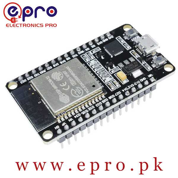
Last checked: 18 October 2026. Product prices and availability, where shown, are a snapshot of Epro listings checked on this date. Confirm the live listing before ordering.
An ESP32 dev board is a practical starting point for Wi-Fi sensor projects, but the first upload should happen before you connect a complicated circuit. This seven-step workflow helps you distinguish a USB problem, an incorrect software target and a wiring fault.

The instructions use Arduino IDE and Espressif’s Arduino core. Menu wording can change between releases, and board variants differ. Follow the board maker’s instructions where they conflict with a generic tutorial.
ESP32 dev board setup checklist
- Your exact board model and chip family.
- A known data-capable USB cable and a reliable USB port.
- Arduino IDE installed from its official source.
- Access to Espressif’s official Arduino core installation instructions.
- No sensors or motor drivers attached during the first test.
If you are comparing boards, see ESP32 board buying guide. The example ESP32 NodeMCU board is one type of development board, not a universal replacement for C3, S3 and camera products.
1. Identify the chip family and connector
Read the module marking and product description. Select documentation for the original ESP32, C3, S3 or other actual target. Inspect the connector rather than assuming every board accepts the same cable. A cable that charges a phone may still lack the data wires needed for programming.
2. Install the supported board package
Use the official Arduino-ESP32 installation guide. Add Espressif’s stable Boards Manager URL exactly as shown there if required, then install the “esp32 by Espressif Systems” package through Boards Manager. Avoid copying outdated package URLs from unrelated downloads.
3. Select the correct board and port
Choose the manufacturer’s board entry when available. A generic development-module profile should match the chip family and memory configuration, not merely contain “ESP32” in its name. Connect the board, compare the port list before and after connection, and choose the new device. If no port appears, test the cable before changing many IDE settings.
4. Check the USB interface driver
Different boards use different USB interfaces. Some contain a USB-to-serial chip; others can expose native USB functions. Identify the interface before installing a driver, and obtain drivers only from the relevant chip manufacturer or operating-system update mechanism. Avoid random “driver pack” installers.
5. Upload a minimal serial test
This sketch avoids assuming that your ESP32 dev board has an onboard LED on a particular pin:Newest in the store


void setup() {
  Serial.begin(115200);
  delay(1000);
  Serial.println("ESP32 serial test");
}

void loop() {
  Serial.println("Board running");
  delay(2000);
}
Open Serial Monitor at 115200 baud after upload. On targets using native USB, the board profile’s USB settings may affect where Serial output appears; check the target documentation. Seeing regular messages confirms that this basic software path works, not that every peripheral has been tested.
6. Diagnose uploads one change at a time
If the IDE cannot connect, disconnect external wiring, close other serial applications and try a known-good cable or USB port. Check that the chosen port is still correct. Some boards require the BOOT button during connection; follow the board’s own procedure rather than holding buttons randomly throughout programming.
A successful compile with a failed upload points to a different stage from a syntax error. Record the full error message. Raising or lowering upload speed can help with some links, but it should not substitute for checking the board target and physical connection.
7. Add one peripheral and retest
After the basic sketch works, add one sensor at a time. Use ESP32 pinout and GPIO guide to avoid input-only, flash and boot-related pins on an original ESP32. Keep signals within 3.3V logic limits. Power motors through suitable drivers and supplies, never directly from the controller’s GPIO.
Frequently asked questions
Why does the power LED light but no port appear?
Power does not prove a working data connection. Test the cable, interface driver and USB port before concluding the board is faulty.
Should I begin with a Wi-Fi example?
A serial-only test isolates the upload path first. Once it works, use an official Wi-Fi example and enter credentials privately; do not publish them in shared code.
Can every ESP32 run the same sketch unchanged?
No. Pin assignments, USB behavior and supported peripherals vary by family. Match the sketch and board profile to the hardware.