


HX711 Arduino: Wiring, Code and Load Cell Calibration

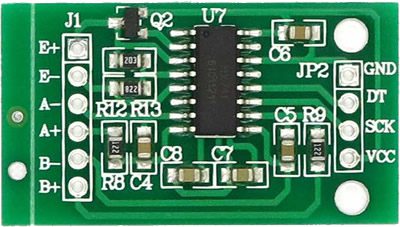
An HX711 Arduino project should begin by reading a stable bridge signal, not by assuming a downloaded constant will produce correct kilograms. A repeatable load path, sensible wiring and a known reference mass are needed before a raw count becomes a useful weight estimate.
This guide uses a conventional 5 V Uno-compatible controller, a module rated for that supply and a compatible four-wire full-bridge load cell. It is an educational bench example, not a certified scale or a safety-critical force measurement system.

1. Identify the HX711 Arduino connections
With power removed, connect the HX711 module VCC to its rated 5 V supply, GND to Uno GND, DOUT to D3 and SCK to D2. Confirm the actual module labels because DT, DOUT and DATA may describe the same function on different boards.
Connect the load cell’s excitation pair to the documented excitation terminals and its signal pair to the intended differential channel, commonly A+ and A−. Do not infer wire colours from a different sensor. The 5 kg cell listing provides its own mapping; verify that mapping against the supplied item.
2. Mount the cell before calibration
Follow the cell’s mechanical mounting arrangement and keep the intended load path clear. The platform must not rub against the base, and the cable must not pull on the moving portion. Use modest bench loads within the sensor rating rather than testing an unknown assembly near its limit.
A three-wire half-bridge sensor is not the same as the four-wire full-bridge cell assumed here. Stop and obtain the correct circuit if the supplied sensor has a different configuration.
3. Install the matching HX711 library
Install the bogde HX711 library through Library Manager. Other libraries with similar names can expose different functions. The official repository explains readiness, tare and calibration operations used in this guide.
The starter sketch reports zeroed counts, not grams. Keep the platform unloaded during its initial tare. If an empty container should be excluded from a later reading, place it consistently before deliberately taring that arrangement.Newest in the store


4. Upload a raw-count test
#include <HX711.h>
HX711 scale;
void setup() {
  Serial.begin(9600);
  scale.begin(3, 2); // DOUT, SCK
  if (!scale.wait_ready_timeout(2000)) {
    Serial.println("HX711 not ready; check wiring");
    while (true) { delay(100); }
  }
  scale.set_scale();
  scale.tare(10); // Platform must be unloaded
}
void loop() {
  if (scale.wait_ready_timeout(1000)) {
    Serial.print("Net counts: ");
    Serial.println(scale.get_value(5));
  } else {
    Serial.println("No ready signal");
  }
  delay(300);
}
Open Serial Monitor at 9600 baud. The readiness check helps identify missing hardware before a read begins, but averaging calls can still wait for subsequent samples. This simple example is not a fully non-blocking or fault-safe acquisition system.
5. Derive your own calibration factor
After a stable unloaded tare, place a known reference mass on the platform and record the average net count C. If the reference mass is M grams, the initial scale factor is C / M counts per gram. Pass that measured factor to set_scale(), then get_units() can report the corresponding gram-based estimate.
A negative factor can reflect the signal direction; do not simply take an absolute value to conceal an unexpected wiring or mounting result. Confirm the physical loading direction and documentation. Never divide by a zero reference mass or use an unstable reading as calibration data.
6. Validate more than one point
Remove and replace the reference mass, test another suitable mass and inspect zero return after unloading. Keep loads within the rating. If results depend strongly on placement, temperature or sideways pressure, improve the mechanical setup and wiring instead of claiming that a single factor guarantees accuracy.
Tare only changes the offset. Repeatedly taring while a load is present can hide the actual measurement. If the sensor disconnects or drifts badly, display a fault rather than presenting a stale value as a fresh weight.
7. Check compatibility before expanding
A 5 V module output must not be assumed safe for a 3.3 V-only GPIO. Review level compatibility before moving this circuit to an ESP32. The HX711 and load-cell buying guide explains bridge types, capacity and ADC-resolution limits. Do not use this starter project for trade, medical or lifting decisions without an appropriately designed and approved measurement system.