


INA310A Current Monitor: 7 Checks for High-Going Comparator Alerts and Gain Choice

INA310A Current Monitor: 7 Checks for High-Going Comparator Alerts and Gain Choice
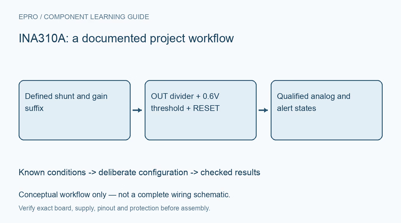
Plan INA310A gain, shunt range and divider thresholds while checking its high-going open-drain alert, reset mode and comparator input limits. This is a documentation-based planning guide, not a report of independent hands-on testing.
1. Specify the gain suffix and accuracy grade
INA310A is a family designation with five fixed-gain choices: 20, 50, 100, 200 and 500 volts per volt. The suffix determines the gain; it is not a software setting. The A and B versions also have different accuracy limits. Identify the complete device marking and expected supply before calculating current. Its operating common-mode range extends from minus four to 110 volts, independently of its 2.7-to-20-volt supply, but this is not galvanic isolation or permission for an unreviewed high-voltage experiment. Manufacturer documentation.
2. Bound the shunt voltage and analog output
For normal positive current, the nominal amplifier output follows shunt voltage times gain, subject to offset, output swing and loading limits. Choose the shunt from allowable voltage loss, power dissipation and fault duration, then check that the highest intended output remains inside the usable range. A high common-mode capability does not make the analog output unbounded. Start with a protected low-voltage resistive load, verify current direction and use Kelvin sense routing so load-path copper does not become an unintended part of the measurement. Manufacturer documentation.
3. Route the comparator input through a deliberate divider
The comparator uses an internal nominal 0.6-volt threshold and a separate CMPIN terminal. An external divider from OUT can set the desired current threshold, but OUT is not automatically limited to a safe comparator input voltage. CMPIN must remain between ground and the lower of 5.5 volts or the device supply. Check the divider over the full amplifier output range, not only at the nominal trip point. Document its physical connection; a correct threshold calculation is useless if CMPIN is left unconnected. Manufacturer documentation.
4. Check threshold arithmetic without copying another monitor
Consider a nominal 50-volt-per-volt variant with a ten-milliohm shunt. Two amps gives twenty millivolts across the shunt and a one-volt output. A divider with twenty kilohms above CMPIN and thirty kilohms below it produces nominally 0.6 volt there. This is illustrative arithmetic, not a validated protection circuit. Include gain, offset, reference and resistor errors. TI recommends keeping the combined divider resistance below 100 kilohms to reduce comparator-input-current effects; a high-resistance divider is not free of threshold error. Manufacturer documentation.
Newest in the store




5. Recognize that overthreshold releases the output high
When CMPIN exceeds the rising threshold, CMPOUT goes high by releasing its open-drain transistor and relying on an external pullup. Below the falling threshold, the transistor pulls CMPOUT low. This polarity is the reverse of many active-low overcurrent alerts. Configure firmware and downstream logic accordingly. Typical comparator hysteresis is eight millivolts, not an exact universal value. Check pullup voltage, controller tolerance and the disconnected-wire state before assuming that a high indication always proves a genuine overcurrent event. Manufacturer documentation.
6. Define transparent operation and retained-event reset
RESET low or open selects transparent comparator behavior. Connecting RESET high selects latching behavior, where an overthreshold event leaves CMPOUT high even after CMPIN falls. Returning RESET low or open releases that retained state, subject to the actual input condition. Do not import reset-pulse timing from another monitor family. Specify a deterministic connection and verify the expected output during startup and recovery. The documented propagation-delay example does not include every controller, switch and load delay in a finished protection chain. Manufacturer documentation.
7. Validate analog readings and alert behavior separately
Record the full gain suffix, shunt value, divider, pullup and reset state in one configuration record. With a current-limited low-voltage source, compare several bounded current levels against an independent reference and check both rising and falling alert behavior. Identify any saturation before interpreting readings or thresholds. Save actual observations separately from datasheet expectations. The device reports current and a comparator condition; it does not interrupt the load itself, so any required shutdown path and fault-energy limit need their own design validation. Manufacturer documentation.
Related reading: INA381 Current Monitor: 7 Checks for Comparator Routing and Alert Timing.
Catalog note: The exact-part search did not return a matching Epro listing during preparation. Check the current catalog; this guide makes no price, availability or included-accessory claim.