


LP5562 LED Driver: 7 Checks for Predictable RGBW Patterns

LP5562 LED Driver: 7 Checks for Predictable RGBW Patterns
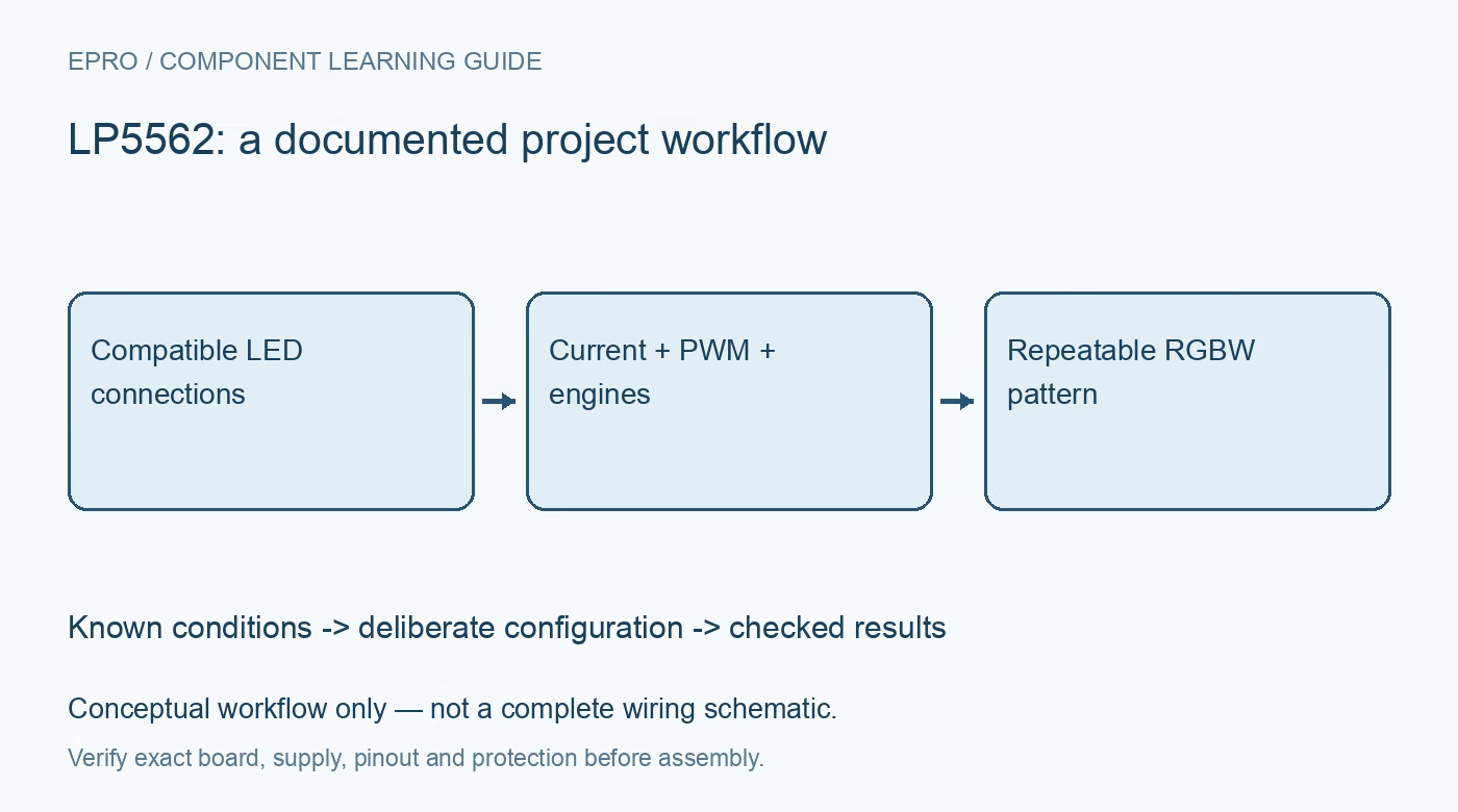
Plan LP5562 RGBW patterns with independent current and PWM settings, three engine mappings, documented program loading and a safe fallback state. This is a documentation-based planning guide, not a report of independent hands-on testing.
1. Separate LP5562 channels from execution engines
LP5562 provides four LED current channels and three program execution engines. Four channels do not imply four independent engines. Decide which channels require direct host control and which should follow an engine-driven pattern. Record the channel-to-engine mapping explicitly. This avoids a common planning mistake in which an RGBW animation is designed around an execution resource that the device does not have, then blamed on the serial interface when the pattern cannot be reproduced. Manufacturer documentation.
2. Verify the LED power topology
Review the current-sink outputs, LED connections and required voltage headroom using the exact circuit documentation. Check the carrier’s supply routing and decoupling rather than assuming every RGBW breakout uses the same connector order. The driver does not make an unsuitable high-power LED load acceptable through software alone. Evaluate LED current ratings, package dissipation and available supply conditions together. Begin with a bounded low-voltage arrangement and do not connect an unknown LED assembly by trial and error. Manufacturer documentation.
3. Treat current setting and PWM as different controls
The device provides separate current and PWM controls. Choose the current setting within the LED and driver limits, then use PWM for the intended brightness modulation. Do not confuse a PWM value with an absolute current specification or assume that equal numeric settings produce equal perceived brightness in different colors. Record both controls when comparing patterns. Optical response and human brightness perception introduce additional considerations beyond the electrical register values used by the host. Manufacturer documentation.
4. Establish a direct-control baseline first
Before introducing engine programs, configure a simple documented direct-control state and check channel identity at conservative settings. Confirm that each output corresponds to the expected LED color or function. Keep a known off state available while investigating unexpected behavior. A basic channel check separates wiring and current-setting issues from program execution errors. It also provides a reproducible reference configuration to restore if a later pattern-loading step fails or communication is interrupted. Manufacturer documentation.
Newest in the store


5. Load programs in the documented engine state
Follow the required engine mode and program-memory loading sequence rather than writing bytes while assuming execution state is irrelevant. Check the instruction format, memory limits and start arrangement against the manufacturer description. Document the program bytes or source representation with a revision identifier. A pattern that occasionally appears after power-up is not evidence of correct loading. The host should know which configuration it intended to install and whether each necessary communication step completed. Manufacturer documentation.
6. Map and start patterns deliberately
Assign the intended outputs to the appropriate engines and verify the mapping before starting execution. Keep transitions between direct PWM control and engine control explicit. Define what happens when the host requests a new pattern during playback, and provide a deliberate stop or fallback state. Autonomous execution reduces the need for repeated host updates, but it does not remove the need to analyze startup, reset and interrupted-configuration behavior in the complete application. Manufacturer documentation.
7. Preserve electrical and visual evaluation boundaries
Retain the LED identity, supply, current settings, PWM values, engine mapping and program revision with every evaluation. If brightness, timing or power is measured, record the instruments and conditions rather than presenting an animation as proof of accuracy. The linked TLC5940 article concerns another driver architecture, not a compatible register map. A responsible LP5562 guide establishes repeatable channel and engine behavior without claiming universal color matching, unlimited load capability or independently measured performance. Manufacturer documentation.
Related reading: TLC5940 LED Driver: 7 Current and Clock Checks.
Catalog note: The exact-part search did not return a matching Epro listing during preparation. Check the current catalog; this guide makes no price, availability or included-accessory claim.