


Measuring Electrical Power Dissipation in Circuits

Measuring Electrical Power Dissipation in Circuits
Measuring electrical power dissipation in circuits helps you understand where electrical power turns into heat, how much power loss your design creates, and whether components can operate safely over time. It is a practical part of circuit design because dissipation affects reliability, circuit efficiency, thermal management, enclosure choices, and the real-world power consumption of the system. With a few measurements and formulas, you can estimate heat generation before it becomes a failure point.
What is power dissipation?
Power dissipation is the rate at which electrical energy is converted into heat or another non-useful form inside a component or circuit. In everyday circuit work, it usually describes the heat produced by resistors, regulators, transistors, diodes, power supplies, cables, and integrated circuits as current flows through them. That heat represents energy dissipation, energy loss, and often reduced efficiency, so it must be measured or estimated carefully.
The basic idea is simple: a circuit receives input power, performs useful work, and loses some energy along the way. The lost portion is dissipation power. In a resistor, nearly all electrical power becomes heat. In a switching power supply, most input power is delivered to the load, while the remaining power loss appears as heat inside magnetic parts, semiconductors, capacitors, and the enclosure.
This is why power dissipation is not just a theoretical number. It tells you whether a resistor is rated high enough, whether a voltage regulator needs a heatsink, whether a printed circuit board needs wider copper, and whether a power supply can run safely in a warm cabinet.

The core formulas for measuring dissipation
The most common power formula is:
P = V × I
Where:
- P is power in watts.
- V is voltage in volts.
- I is current in amps.
If you know the voltage across a component and the current through it, you can calculate power dissipation directly. For a resistor, Ohm’s law gives two more useful forms:
- P = I² × R when current and resistance are known.
- P = V² ÷ R when voltage and resistance are known.
These equations are the foundation of how to calculate power dissipation in many common circuits. For example, if a resistor has 5 V across it and 0.1 A flowing through it, it dissipates 0.5 W. In practice, you would usually choose a resistor rated comfortably above that value, because ratings depend on airflow, ambient temperature, board layout, and long-term operating conditions.
For an entire circuit, compare input power and output power:
- Input power = input voltage × input current
- Output power = output voltage × output current
- Power loss = input power − output power
- Circuit efficiency = output power ÷ input power × 100%
This method is especially useful for converters, motor drivers, LED drivers, amplifiers, and power modules. It also connects power dissipation directly to power consumption: the system may draw a certain amount of energy from the source, but not all of that energy becomes useful output.
How do you calculate power dissipation in real circuits?
To calculate power dissipation in real circuits, identify the component or system boundary, measure voltage and current under realistic load conditions, then apply the correct power equation. The key is to measure the circuit as it actually operates, not only under ideal bench conditions.
A practical workflow looks like this:
Define the measurement point Decide whether you are measuring one component, one board section, or the whole circuit. A regulator’s dissipation is different from the total power loss of the complete device.
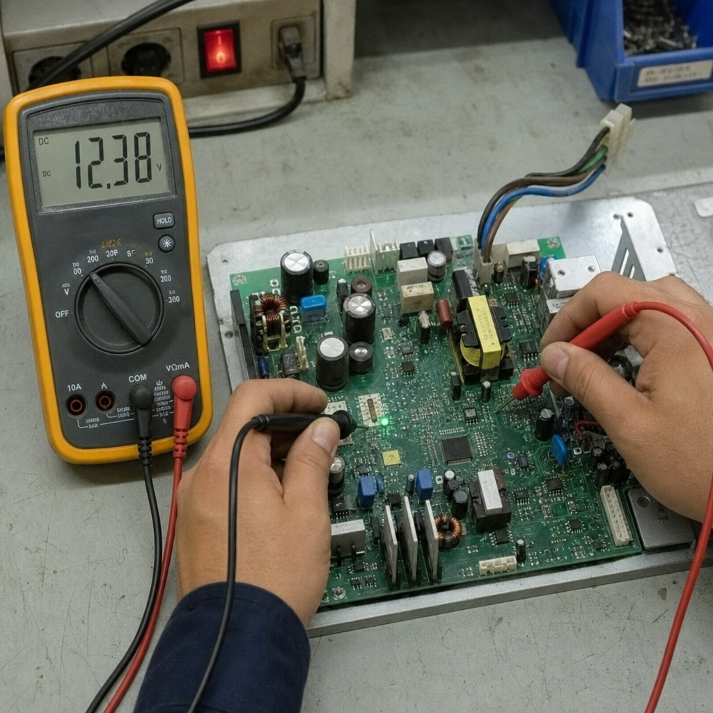
Measure voltage across the part Use a multimeter, oscilloscope, or differential probe depending on the circuit. For DC circuits, a multimeter is often enough. For switching circuits, waveforms may change quickly, so average and RMS values matter.
Measure current through the part Current can be measured with an ammeter in series, a current probe, or a known sense resistor. Avoid adding excessive resistance that changes circuit behavior.
Apply the right equation Use P = V × I for direct voltage-current measurements, or resistor-specific formulas when appropriate.
Compare against ratings Check component power ratings, temperature limits, derating guidance, and board-level thermal conditions. A part that survives briefly on the bench may not be suitable inside a sealed enclosure.
Validate with temperature Use a thermal camera, thermocouple, or temperature sensor to confirm that calculated heat dissipation matches reality. Electrical math and thermal behavior should tell the same story.
A power dissipation calculator can speed up these steps, especially when checking resistors, regulators, or efficiency numbers. However, the calculator is only as reliable as the values entered. Use measured voltage and current whenever possible, and remember that load current, input voltage, duty cycle, and ambient temperature can change the final result.
Newest in the store


Component-level heat generation in common parts
Different parts dissipate power in different ways. Understanding the source of heat generation helps you solve the right problem instead of only treating the symptom.
Resistors
Resistors are the clearest example of electrical power becoming heat. Current through resistance creates heat according to P = I² × R, which means dissipation rises quickly as current increases. If a resistor runs hot, consider a higher wattage part, a different resistance value, multiple resistors sharing the load, or a layout with better copper area.
Linear regulators
A linear regulator dissipates the voltage drop from input to output multiplied by load current. If a 12 V input regulator supplies 5 V at 0.5 A, the regulator must dissipate 3.5 W. That can become a serious thermal management issue, even though the circuit seems simple and quiet electrically.
Switching regulators and power supplies
Switching supplies are usually more efficient than linear regulators, but they still create power loss. Losses may occur in MOSFET switching, diode conduction, inductor resistance, transformer losses, control circuitry, and capacitors. When evaluating delta electronics power supply heat dissipation or comparing delta electronics power and heat dissipation data for a specific module, look for efficiency curves, load conditions, airflow assumptions, and ambient temperature limits in the official documentation for that exact model.
Diodes, MOSFETs, and transistors
Semiconductors often dissipate power through voltage drop, on-resistance, switching transitions, or leakage. A diode’s dissipation can be estimated from forward voltage multiplied by current. A MOSFET may need conduction loss and switching loss estimates, especially in high-current or high-frequency designs.
Power dissipation and circuit efficiency work together
Power dissipation and circuit efficiency are two sides of the same problem. If more input power becomes useful output, less becomes heat. If more energy becomes heat, efficiency drops and the design may require larger parts, more airflow, better copper, or additional cooling.
For a complete power stage, efficiency gives a quick view of the thermal challenge. A 90% efficient converter delivering 100 W to a load loses about 11.1 W internally because it must draw about 111.1 W from the source. That loss becomes heat dissipation somewhere in the system. A small enclosure with poor airflow may struggle with that heat, while an open chassis with metal mounting may handle it easily.
Improving efficiency can reduce:
- Internal temperature rise.
- Fan size or airflow requirements.
- Stress on capacitors and semiconductors.
- Wasted battery energy.
- Long-term reliability risks.
- Unwanted energy loss in always-on equipment.
The practical lesson is to treat efficiency as a thermal design tool, not just a performance specification.
Measuring safely and accurately
Accurate dissipation measurements require both electrical care and thermal awareness. Small mistakes can produce misleading numbers or damage equipment.
Use this checklist before testing:
- Confirm the circuit voltage and current are within the range of your meter or probe.
- Use properly rated leads, probes, and current shunts.
- Measure under the load conditions the product will actually experience.
- Let the circuit reach thermal steady state before recording temperature.
- Watch for pulsed loads, startup surges, and duty-cycle changes.
- Avoid touching energized circuits or hot components.
- Record ambient temperature, airflow, input voltage, and load current with the reading.
For low-power DC circuits, a multimeter may be enough. For fast switching circuits, an oscilloscope with suitable probes may be necessary because voltage and current waveforms are not constant. For high-voltage, high-current, or mains-connected equipment, use proper isolation and qualified test procedures.
Thermal management turns measurements into reliability
Once you know where power loss occurs, the next step is moving heat away from sensitive components. Thermal management is not only about adding a heatsink at the end. It begins with component choice, continues through layout, and ends with enclosure-level cooling.
Useful thermal strategies include:
- Choose efficient topologies: A switching regulator may be better than a linear regulator when voltage drop and load current are high.
- Derate components: Avoid running parts continuously at their maximum rating.
- Use copper wisely: Larger copper areas and thermal vias can spread heat across the PCB.
- Improve airflow: Even modest airflow can lower component temperature when the layout supports it.
- Separate heat-sensitive parts: Keep electrolytic capacitors, sensors, and precision references away from hot components.
- Use heatsinks or metal mounting: Mechanical design can become part of the heat path.
- Check enclosure effects: A board that runs cool in open air may overheat in a sealed plastic case.
Good circuit design balances electrical performance, cost, space, safety, and heat. The best solution is often a combination of lower dissipation, better spreading, and realistic operating margins.
Common mistakes that lead to hidden power loss
Many dissipation problems start with assumptions that seem reasonable early in a project. A design may work at room temperature on the bench but fail when the load increases, the enclosure closes, or ambient temperature rises.
Watch for these common mistakes:
- Calculating only typical load instead of worst-case load.
- Ignoring voltage tolerance from adapters, batteries, or supplies.
- Forgetting that resistance increases with temperature in some conductors.
- Using component ratings without checking derating curves.
- Measuring input power but not locating where losses occur.
- Treating a power dissipation calculator result as final proof.
- Assuming a high-efficiency supply has no meaningful heat generation.
A better habit is to calculate early, measure under real conditions, and verify temperature after the design is assembled as it will be used.
Practical takeaway
Power dissipation is the link between electrical behavior and physical heat. When you measure voltage, current, power consumption, and temperature together, you can see where energy dissipation occurs and make better decisions about components, layout, cooling, and overall circuit efficiency.
Start with the basic formulas, use a power dissipation calculator for quick checks, and confirm important results with real measurements. Whether you are sizing a resistor, evaluating a regulator, or reviewing heat dissipation in a power supply, the goal is the same: reduce power loss where possible and manage the remaining heat safely.