


OPA388 Precision Op Amp: 7 Checks for Zero-Crossover Operation

OPA388 Precision Op Amp: 7 Checks for Zero-Crossover Operation
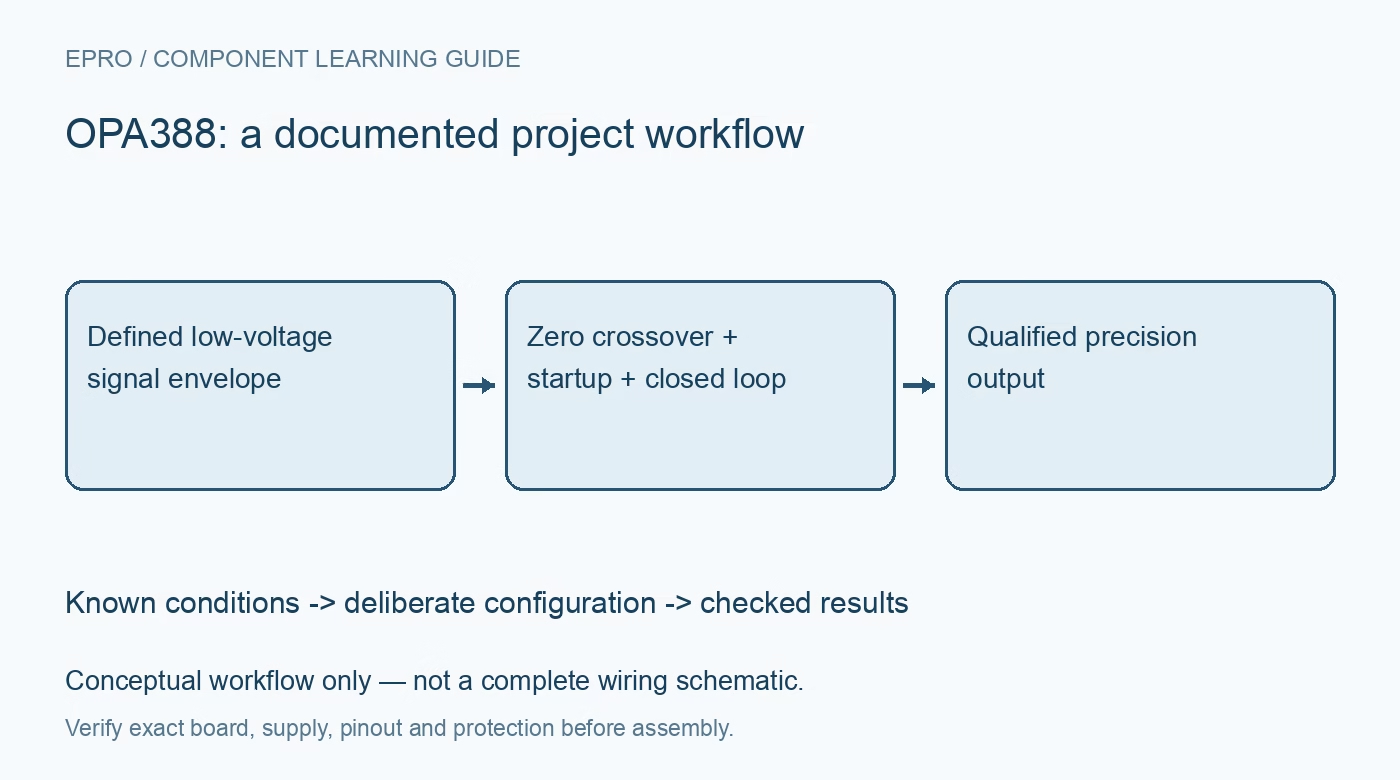
Design an OPA388 precision stage with seven checks for low-voltage rails, zero-crossover input operation, startup accuracy, overload current and ADC settling. This is a documentation-based planning guide, not a report of independent hands-on testing.
1. Keep the low-voltage supply range explicit
OPA388 is a precision amplifier for a total operating supply of 2.5 V to 5.5 V. Do not treat it as a drop-in substitute for a higher-voltage precision family merely because the package looks familiar. With split rails, the total positive-to-negative supply remains subject to that limit. Check startup, overshoot and unpowered input conditions as well as the nominal rail. Record the single, dual or quad device and exact package pinout before using a reference schematic. Manufacturer documentation.
2. Understand the zero-crossover input architecture
The input common-mode range extends slightly beyond both supply rails under the specified conditions. A single differential input pair and internal low-noise charge pump avoid the complementary-input crossover transition found in some rail-to-rail amplifiers. This feature addresses a particular source of nonlinearity; it is not zero distortion under every load or frequency. Review the complete common-mode and differential-input limits rather than confusing the extended linear range with unlimited tolerance to an externally driven input. Manufacturer documentation.
3. Reserve output headroom independently of input range
True rail-to-rail input operation does not guarantee that the output can deliver either rail exactly under load. Calculate the required output at the intended gain, source range and common-mode condition, then compare it with the specified swing and drive limits. A voltage follower is especially easy to misjudge near its output boundary. Include the following ADC or cable load in this review. Prevent clipping before interpreting a flat output as excellent DC stability or calibration repeatability. Manufacturer documentation.
4. Allow startup offset correction to settle
The internal offset-correction process needs approximately one millisecond after power-up to reach the specified offset accuracy. This is an approximate device behavior, not an unconditional board-ready timer. External reference startup, filters, source impedance and any ADC acquisition sequence can require additional time. Separate power-valid, amplifier-ready and measurement-ready states in the host design. If the amplifier is power-cycled to save energy, include that startup interval and the complete analog-chain recovery in every acquisition cycle. Manufacturer documentation.
Newest in the store


5. Review overload input currents before recovery tests
When the feedback loop cannot maintain linear operation, a differential input voltage can develop and increase input current through internal structures. Very low normal bias current is therefore not a promise of negligible current during overload. Check the manufacturer protection discussion and absolute limits when connecting a high-impedance sensor, multiplexer or externally powered source. Use bounded tests and suitable protection. A recovery experiment should not exceed pin ratings just to observe how quickly the output returns to a plausible value. Manufacturer documentation.
6. Qualify noise and settling in the complete loop
Zero-drift and zero-crossover design remove specific error mechanisms, but the external resistors, source, feedback network and sampling system still contribute noise and settling limits. The internal EMI filtering is not a complete application anti-alias filter. Choose bandwidth intentionally and assess capacitive-load stability with the actual circuit. Compare small and large steps against a defined acceptance band rather than using gain bandwidth or a typical settling headline alone to declare the ADC input accurate at its sampling instant. Manufacturer documentation.
7. Measure common-mode linearity and startup repeatability
Use a suitable reference setup to test several signal levels across the allowed common-mode range, preserving gain, load, supply and temperature information. Assess offset, noise bandwidth and dynamic recovery as separate observations. Repeat power-up acquisitions if low-duty-cycle operation is intended, and retain rejected startup samples for diagnosis. Avoid translating a microvolt offset headline into a claim of system accuracy. Release a precision result only within the conditions actually qualified for the assembled stage. Manufacturer documentation.
Related reading: OPA189 Precision Op Amp: 7 Checks for Headroom and Zero Drift.
Catalog note: The exact-part search did not return a matching Epro listing during preparation. Check the current catalog; this guide makes no price, availability or included-accessory claim.