


PCM1803A Audio ADC: 7 Checks for Oversampling and Startup Data

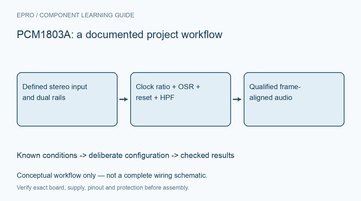
PCM1803A Audio ADC: 7 Checks for Oversampling and Startup Data
Configure PCM1803A audio capture with seven checks for dual supplies, clock ratios, OSR limits, startup-valid timing, HPF bypass and stereo data format. This is a documentation-based planning guide, not a report of independent hands-on testing.
1. Provide the separate analog and digital rails
PCM1803A is a stereo audio ADC with a nominal 5 V analog supply and 3.3 V digital supply, not the single-rail arrangement of some newer devices. Check the recommended operating ranges and every host interface level, including unpowered states. Route and decouple the analog and digital domains according to the manufacturer layout guidance. The reference pins need their prescribed capacitors and are not convenient general-purpose outputs. Confirm the exact twenty-pin package drawing before connecting a board based on another audio ADC. Manufacturer documentation.
2. Design for the single-ended analog input
The documented input is single ended, with a nominal full-scale span of 3 V peak to peak under specified conditions. Review biasing, coupling and source impedance using the application circuit rather than connecting a bipolar audio waveform directly by assumption. Check both channels for clipping at the actual source level. The reference network and coupling capacitors influence startup and low-frequency behavior, so an electrically valid digital interface does not by itself establish a correctly conditioned audio signal. Manufacturer documentation.
3. Assign clock ownership and a supported ratio
SCKI must receive a suitable system clock. In slave mode, the device can detect supported clock ratios, including 256, 384, 512 and conditionally 768 times the sample rate. Master mode uses the MODE pins to select the documented arrangement and does not support every slave-mode option. Check the sampling-frequency table rather than multiplying any rate by any ratio. Ensure only one device drives BCK and LRCK, and verify those frequencies at the ADC pins before judging the received samples. Manufacturer documentation.
4. Keep oversampling selection within its rate limit
OSR low selects sixty-four-times oversampling, while OSR high selects one-hundred-twenty-eight-times operation only for sample rates at or below 48 kHz. A strap appropriate for 44.1 kHz cannot simply remain unchanged when moving to 96 kHz. Treat OSR, clock ratio and sample rate as one reviewed configuration. The manufacturer recommends a power-down cycle when changing sampling rate, interface mode, data format or oversampling control, so do not assume a live host register change is a complete reconfiguration. Manufacturer documentation.
Newest in the store


5. Wait beyond reset before accepting audio samples
At power-on, the ADC holds digital output at zero through its reset sequence. After the specified reset release, the datasheet gives a further interval of 4480 divided by sample rate before output becomes valid. At 48 kHz, that interval alone is about 93 milliseconds, in addition to the earlier reset requirements. Distinguish this intentional startup behavior from a silent input or failed data wire. Track sample validity explicitly and include analog coupling-network settling in the complete acceptance policy. Manufacturer documentation.
6. Select format and HPF behavior deliberately
The FMT pins select documented I2S, left-justified or right-justified formats with the relevant word lengths. Configure the receiver to match both format and channel alignment. BYPAS low retains the high-pass filter that rejects DC; BYPAS high bypasses it and allows input DC and internal offset into the output data. Choose the setting for the application, not just for a visually centered waveform. A mean close to zero with the filter active is not proof that the analog input bias is correct. Manufacturer documentation.
7. Verify synchronization before measuring audio quality
The converter requires synchronized system and frame clocks; loss and recovery of synchronization can produce zero or undefined output intervals and discontinuities. Capture known low-level signals on one channel at a time to confirm ordering, format and polarity, then assess clipping, noise and distortion at a stated bandwidth. Record rails, sample rate, OSR, clock ratio, BYPAS and reset timing with the capture. Typical SNR and nominal twenty-four-bit data width do not guarantee equivalent resolution or noise performance on the assembled board. Manufacturer documentation.
Related reading: PCM1861 Audio ADC: 7 Checks for Hardware Straps and Clocks.
Catalog note: The exact-part search did not return a matching Epro listing during preparation. Check the current catalog; this guide makes no price, availability or included-accessory claim.