


TB6612FNG vs DRV8833: 7 Motor Driver Buying Checks

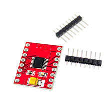
TB6612FNG and DRV8833 are both familiar names for dual H-bridge motor drivers, but they are not interchangeable chip identities or pin-for-pin substitutes. A product title containing both names needs clarification before a wiring diagram is chosen.
This guide addresses that exact buying problem. It compares the checks that matter and deliberately avoids presenting one universal hookup for an unverified board. Confirm the actual supplied IC marking and module pinout before applying power.

TB6612FNG and DRV8833 listing price
| Listed item | Price (PKR) | Project role |
|---|---|---|
| TB6612 / DRV8833 Dual Motor Driver Module – 1A H-Bridge for Arduino & Robotics | 550 | Combined TB6612 / DRV8833 title; confirm actual supplied driver |
Price snapshot: Epro listings checked on 19 October 2026. Confirm the current price, availability, delivery charges and package quantity on the linked page before ordering. These are dated listing prices, not a quotation or an independent performance test.
The Epro dual-motor-driver listing names both TB6612 and DRV8833. Its displayed price does not establish which chip a particular shipment contains or that both versions share electrical limits. Ask for the exact variant, clear board photographs and a matching pinout before ordering for an existing design.
1. Identify the actual IC, not just the board colour
Read the package marking and compare it with the manufacturer’s document. Similar connector layouts and marketplace names are not sufficient identification. A library selected for the wrong control interface may compile while driving the board incorrectly.
If the marking cannot be verified, do not infer the identity from a tutorial photograph. Resolve the ambiguity before connecting a motor, especially when replacing a driver in a previously working circuit.
2. Compare recommended operating conditions
The Texas Instruments DRV8833 datasheet specifies a 2.7–10.8 V motor-supply operating range. The linked Toshiba TB6612FNG document shows a 4.5–13.5 V motor-supply application circuit and a separate logic supply.
Use the exact device revision’s recommended conditions and the module’s limits. Do not replace a recommended operating range with a higher absolute-maximum number from a headline. Motor supply, logic supply and input voltage are separate constraints.
3. Account for stall and startup current
A motor’s free-running current is not the maximum current it demands. Startup or a blocked shaft can produce a much larger current. Choose a driver using the motor’s documented stall conditions and the intended supply, not only a casual no-load measurement.
IC current figures are also conditional on package, thermal design and operating circumstances. A peak rating is not a continuous module rating, and a small breakout may dissipate heat differently from the manufacturer’s reference board.Newest in the store


4. Match the control interface
The TB6612FNG interface includes direction inputs, separate PWM inputs and STBY. The DRV8833 uses paired bridge-control inputs and nSLEEP, with different control and current-regulation details. The relevant truth tables must match the actual chip.
A sleep or standby input held in the inactive state can make a correctly wired motor appear dead. Conversely, a copied sketch can enable movement unexpectedly. Define startup states deliberately rather than guessing that every pin called enable has the same behaviour.
5. Review logic levels and grounding
A 3.3 V controller and a 5 V controller may require different logic-supply choices on a driver with a separate VCC pin. Check the specified HIGH threshold against the controller’s guaranteed output, not merely a typical voltage.
The signal reference must be arranged correctly, with motor-current return paths kept from creating avoidable noise in the logic wiring. Do not route motor power through a GPIO or assume a controller’s small regulator is a suitable motor supply.
6. Distinguish protection features from system safety
Thermal shutdown, undervoltage behaviour or current regulation does not make an arbitrary motor installation safe. Board implementation, wiring, decoupling and load energy still matter. Check whether a module actually implements the current-sense arrangement expected by the chip.
Do not join two bridge outputs or parallel channels unless the exact manufacturer and module guidance permits the arrangement. Do not connect household mains or use these low-voltage hobby drivers as a certified protective stop.
7. Establish a controlled first test
After identifying the board, use a small suitable motor, a protected supply and a setup that prevents unexpected wheel or mechanism movement. Power down before changing leads. Start with a documented single-channel example for that exact interface, not a combined-name tutorial.
If the actual product remains ambiguous, choose a clearly identified replacement instead of forcing a guessed pinout. The best buying decision is the driver whose electrical and thermal requirements can be verified for the intended motor, not the board with the most attractive peak-current headline.