


TCA9544A I2C Mux: 7 Checks for One Channel and Interrupt Routing

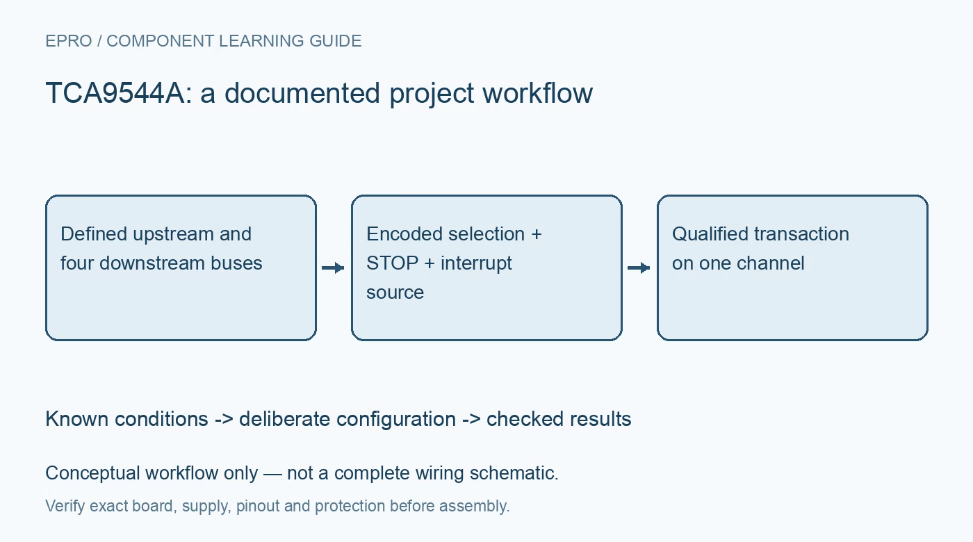
TCA9544A I2C Mux: 7 Checks for One Channel and Interrupt Routing
Plan TCA9544A routing with seven checks for encoded channel selection, STOP activation, interrupt status, voltage translation and stuck-bus recovery. This is a documentation-based planning guide, not a report of independent hands-on testing.
1. Recognize a one-of-four multiplexer, not a channel mask
TCA9544A connects the upstream SDA/SCL pair to one of four downstream pairs. It is not a four-bit independent channel-enable switch. The low control bits encode a channel number plus an enable bit: 0x04 selects channel zero, 0x05 channel one, 0x06 channel two and 0x07 channel three. With the enable bit clear, no channel is selected. Importing a one-hot mask routine from a different mux can therefore select the wrong bus or disconnect every downstream device. Manufacturer documentation.
2. Set the upstream address independently of downstream devices
Three address pins select the multiplexer seven-bit address from 0x70 through 0x77. A downstream sensor can retain the same address as an identical sensor on another isolated channel, provided only the intended channel is connected. The mux itself remains an upstream device that the host must address first. Record each logical sensor as a combination of mux address, channel number and downstream address; a sensor address alone is not a unique identifier in this topology. Manufacturer documentation.
3. End channel selection with a STOP condition
The selected downstream channel becomes active after the control-byte transaction ends with STOP. The datasheet requires STOP immediately after the acknowledge cycle. Do not combine the selection write and downstream access using a repeated START that omits the required STOP. Confirm the sequence with a logic analyzer: upstream mux address, control byte, acknowledge, STOP, then a new transaction for the selected target. Read back selection when diagnosing faults rather than assuming a software variable matches the actual switch state. Manufacturer documentation.
4. Design pull-ups and voltage translation for every segment
The pass-switch architecture permits documented level translation between suitable I2C voltage domains, but each bus segment still needs correctly chosen pull-ups. Check the mux supply, pass-voltage characteristics, input thresholds, sink current and combined capacitance when a channel is connected. This is not a universal logic translator for push-pull signals or a galvanic isolator. Start at a conservative bus speed, measure rise time on both sides, and include module pull-ups that may already be fitted in the effective resistance. Manufacturer documentation.
Newest in the store


5. Read interrupt status even for an unselected channel
Four active-low interrupt inputs feed the upstream open-drain INT output. A downstream channel does not need to be selected for its interrupt to be detected. On control-register reads, bits four through seven identify asserted interrupt inputs for channels zero through three. These status bits should not be mistaken for extra channel-enable bits. Tie unused interrupt inputs to VCC as specified and provide an appropriate INT pull-up. Multiple channels can simultaneously report pending events even though only one data path is connected. Manufacturer documentation.
6. Clear the originating device, not merely the mux status
After identifying a pending channel, select it with the required STOP and service the device or devices responsible for its interrupt. Reading the mux does not substitute for the downstream device-specific clear sequence. More than one source can share a channel, so the handler must reconcile all relevant sources before concluding service is complete. Re-read interrupt status and use bounded servicing to avoid starvation. Preserve application-level event evidence before a downstream status read clears it. Manufacturer documentation.
7. Plan recovery for a channel that holds the bus low
Power-on reset deselects all channels. This device does not provide a separate reset pin to borrow from another TCA95xx part. If a selected target holds upstream SDA low, ordinary channel-control writes may no longer be possible. Design an appropriate system-level recovery path, such as controlled downstream power or a reviewed mux supply reset, instead of assuming software can always disconnect a stuck segment. Test recovery with a safe logic fixture and verify that restored communication starts from known selection and interrupt states. Manufacturer documentation.
Related reading: TCA9545A I2C Switch: 7 Checks for Channel Masks and Interrupts.
Catalog note: The exact-part search did not return a matching Epro listing during preparation. Check the current catalog; this guide makes no price, availability or included-accessory claim.