


TCA9545A I2C Switch: 7 Checks for Channel Masks and Interrupts

TCA9545A I2C Switch: 7 Checks for Channel Masks and Interrupts
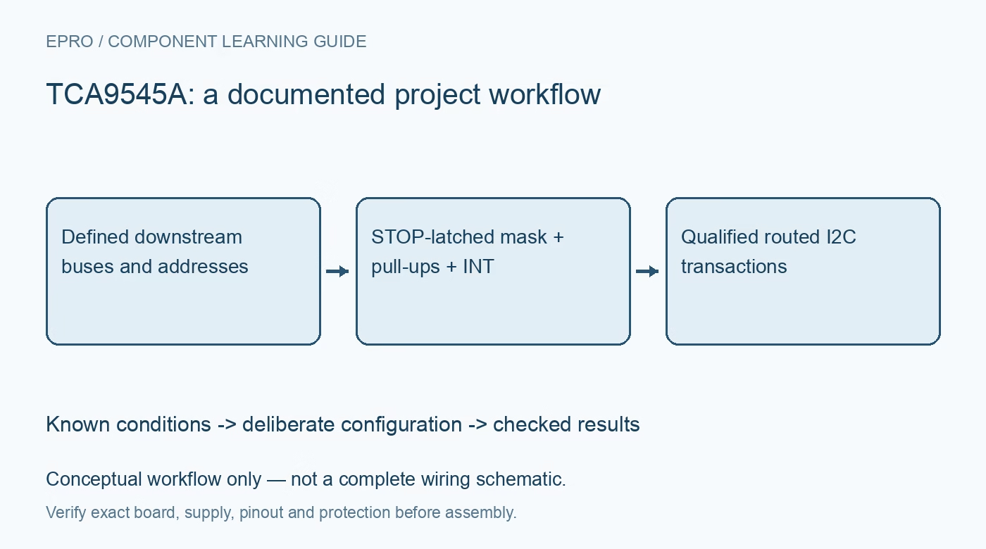
Plan a TCA9545A bus tree with STOP-latched channel masks, address-conflict control, downstream pull-ups, interrupt routing and hardware reset recovery. This is a documentation-based planning guide, not a report of independent hands-on testing.
1. Draw the complete bus tree and address map
TCA9545A connects one upstream I2C pair to any selected combination of four downstream pairs. It is a bus switch, not four independent bus controllers or a GPIO expander. Document its hardware address, every target address and the allowed channel combinations. A switch can isolate duplicate-address devices only while conflicting branches are kept separate. Enabling two branches containing the same address can make both targets respond, even though each branch worked correctly during an individual test. Manufacturer documentation.
2. Write a channel mask rather than a channel number
The lower four control bits enable downstream branches individually. A mask selecting two bits connects two buses, not the second channel in a numbered list. Keep symbolic masks in firmware and validate them against the physical connector labels. The upper control-register bits report interrupt-related status and have a different role. Avoid a generic multiplexer driver that assumes exactly one channel can be active or that treats every control bit as freely writable selection data. Manufacturer documentation.
3. End selection writes with the required STOP
The manufacturer specifies that a selected channel becomes active after a STOP condition follows the control-register write. A repeated-start transaction substituted for that STOP does not satisfy the documented switching sequence. Separate branch selection from the following target transaction so the route is established at the intended time. Verify the host library actually emits the required bus condition. A successful acknowledgement of the switch address proves the control byte was received, not that an arbitrary immediate downstream transfer is already routed correctly. Manufacturer documentation.
4. Design pull-ups and translation for each connected segment
The pass-gate architecture supports documented bus-level translation with appropriate supply choice and separate pull-ups. It is not galvanic isolation or an unrestricted bidirectional voltage converter. Check recommended operating conditions, input tolerance, pull-up rails, rise time and sink current on upstream and downstream buses. When several channels are enabled, their capacitances and pull-up paths interact. A branch that meets timing alone may fail when combined with others. Evaluate the largest allowed mask at the intended bus speed. Manufacturer documentation.
Newest in the store


5. Use interrupt status even when a branch is deselected
The four interrupt inputs can signal through the common open-drain interrupt output independently of whether the corresponding I2C branch is currently enabled. This lets the host learn which downstream area needs service before routing its bus. Read the control-register status using the documented bit mapping, select the relevant branch, and interrogate the actual target device. More than one device can share a branch interrupt, so service all relevant sources. The switch does not decode target-specific events or clear their internal causes. Manufacturer documentation.
6. Give hardware RESET an upstream recovery role
RESET clears the switch state machine and deselects channels under the documented timing conditions, allowing recovery from some downstream stuck-low situations. Keep its pull-up and host control accessible even when normal I2C commands cannot complete. Resetting the switch does not reset a faulty target on a disconnected branch or cure bad wiring. After recovery, restore only the intended route and confirm bus-high levels before resuming traffic. Power-up also starts with all branches deselected, so firmware must establish its route explicitly. Manufacturer documentation.
7. Test collisions, interrupts and fault isolation deliberately
With noncritical devices, verify every individual route, each allowed combined mask and the required STOP sequence. Assert an interrupt from a deselected branch and confirm the host locates and services the correct target. Test hardware reset with a safely simulated downstream low condition without shorting incompatible supply rails. Record masks, addresses, pull-ups, bus speed and recovery policy. This manufacturer-based guide makes no independent hot-insertion, timing-margin or fault-isolation guarantee for an untested bus tree. Manufacturer documentation.
Related reading: TCA9546A I2C Switch: 7 Checks for a Predictable Bus Tree.
Catalog note: The exact-part search did not return a matching Epro listing during preparation. Check the current catalog; this guide makes no price, availability or included-accessory claim.