


TCS3200 Color Sensor Price: 7 Buying Checks

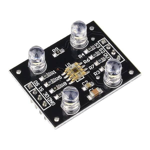
A TCS3200 color sensor price comparison should consider the full optical setup, not just the cheapest board. The sensor provides light-dependent pulse frequencies; useful colour recognition also depends on illumination, geometry, calibration and the objects being inspected.
This guide covers Epro’s current module listings and the questions to ask before choosing one. It does not claim independently tested colour accuracy, guaranteed material identification or suitability for medical test interpretation.

TCS3200 color sensor price and module options
| Listed item | Price (PKR) | Project role |
|---|---|---|
| SR078 TCS230 TCS3200 Detector Module Color Recognition Sensor in Pakistan | 1,500 | SR078 listing describing a TCS3200D sensor and illumination LEDs |
| GY-31 TCS230 TCS3200 Color Sensor Recognition Module | 1,650 | GY-31 colour-sensor module listing |
Price snapshot: Epro listings checked on 18 October 2026. Confirm the current price, availability, delivery charges and package quantity on the linked page before ordering. These are dated listing prices, not a quotation or an independent performance test.
The SR078 product description explicitly discusses the TCS3200D and four white illumination LEDs. The GY-31 listing provides less detailed documentation. Verify the supplied chip marking, pin labels, LED arrangement and package rather than assuming similar names prove identical boards.
1. Understand light-to-frequency output
The ams TCS3200 datasheet describes a programmable colour light-to-frequency converter. It outputs a square wave whose frequency is proportional to the light reaching the selected photodiode group.
It does not directly send three calibrated RGB bytes or a colour name over I2C. A controller selects a filter and measures pulses. Software must then interpret those measurements within the actual optical arrangement.
2. Check red, green, blue and clear selection
The chip contains groups of red-filtered, green-filtered, blue-filtered and unfiltered photodiodes. S2 and S3 select the active group. The clear group is not a fourth primary colour; it responds without the coloured filter.
Read the selection table for the actual chip. The combined TCS230/TCS3200 wording used in some listings should not replace verification of what is supplied. Do not select a library solely because its name contains a similar sensor number.
3. Match supply and logic voltage
The documented chip supply range is 2.7–5.5 V. A finished module can add illumination and other components whose requirements must also be checked. A conventional 5 V Uno is a practical starting point for a compatible 5 V module arrangement.
Newest in the store


A sensor powered at 5 V can produce a high output inappropriate for a 3.3 V-only controller input. Match the output level and controller limits before wiring. A wide chip supply range is not proof that every assembled module behaves identically at every voltage.
4. Choose a manageable frequency scale
S0 and S1 select power-down, 2%, 20% or 100% output scaling. Scaling changes the output frequency to suit the measurement technique. It does not directly adjust the physical brightness of the object or turn raw readings into standard colour coordinates.
A slower pulse rate can make a simple pulse-width demonstration easier to observe. A faster application needs a deliberately chosen counter or timing method. Do not infer the finished system’s object-sorting speed from the chip’s maximum frequency alone.
5. Control the optical environment
Keep sample distance, angle and illumination consistent. A glossy object can reflect a lamp differently when moved slightly, and a dark sample can produce much weaker signals than a pale one. An enclosure or shield can reduce unwanted ambient-light variation.
Onboard white LEDs help create a light source, but they do not make the sensor immune to room lighting or shadows. Do not promise recognition in every ambient condition without testing that exact arrangement across the intended operating range.
6. Budget for calibration and uncertainty
Collect readings from reference samples under the intended geometry. White and dark references can help establish useful relative ranges, but a simple linear mapping is not automatically a colourimetric calibration. Test multiple samples of the materials the project will actually see.
Raw frequency or pulse width should be labelled as such. A printed 0–255 value does not prove camera-equivalent RGB, a measured wavelength or a recognised paint standard. Classification thresholds need validation and an explicit uncertain or unknown outcome.
7. Start with raw filter readings
Use the TCS3200 colour sensor Arduino wiring and code guide to compare pulse widths before naming colours. Keep the first project observational and low risk. Industrial inspection, safety decisions and medical readings require an appropriately validated measurement system rather than an unverified hobby demonstration.