


TCS3200 Color Sensor Arduino: Wiring and Code Guide

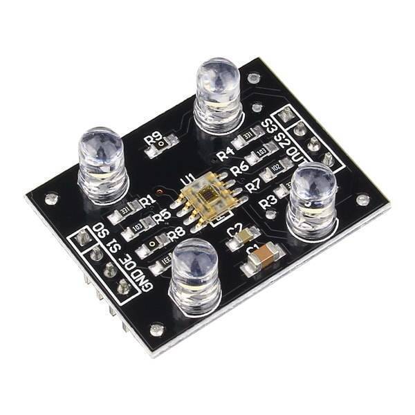
A TCS3200 color sensor Arduino test should first report raw pulse measurements for the selected filters. Printing a colour name too early can hide wiring problems and make uncalibrated thresholds look more reliable than they are.
This example uses a conventional 5 V Uno-compatible board and a compatible TCS3200 module. It compares low-pulse widths rather than claiming calibrated RGB values, exact wavelength measurement or dependable sorting of every material.

1. Check the actual module and output enable
Find VCC, GND, S0, S1, S2, S3 and OUT on the actual TCS3200 module. If OE is exposed, connect it appropriately for enabled operation: the chip’s output enable is active low. Some modules already fix that connection on the board.
Do not leave configuration inputs floating. The manufacturer datasheet explains the filter and scaling tables. Work from the actual chip and board labels, not a pin order taken from an unrelated module picture.
2. Wire the TCS3200 color sensor Arduino test
| Module connection | Conventional Uno destination |
|---|---|
| VCC | 5 V for a compatible rated module |
| GND | GND |
| S0, S1 | D4, D5 |
| S2, S3 | D6, D7 |
| OUT | D8 |
| OE, if exposed and not already fixed | GND to enable |
Disconnect USB during assembly and use short connections. A 5 V output must not be transferred directly to a 3.3 V-only controller input. Changing boards requires another electrical review, not merely changing the digital pin numbers.
3. Upload a timeout-aware pulse-width example
const byte S0 = 4, S1 = 5, S2 = 6, S3 = 7;
const byte OUT_PIN = 8;
unsigned long readLowWidth(byte a, byte b) {
  digitalWrite(S2, a);
  digitalWrite(S3, b);
  delay(10);
  return pulseIn(OUT_PIN, LOW, 100000UL);
}
void setup() {
  Serial.begin(9600);
  pinMode(S0, OUTPUT); pinMode(S1, OUTPUT);
  pinMode(S2, OUTPUT); pinMode(S3, OUTPUT);
  pinMode(OUT_PIN, INPUT);
  digitalWrite(S0, LOW);
  digitalWrite(S1, HIGH); // 2% frequency scaling
}
void loop() {
  unsigned long r = readLowWidth(LOW, LOW);
  unsigned long g = readLowWidth(HIGH, HIGH);
  unsigned long b = readLowWidth(LOW, HIGH);
  if (r == 0 || g == 0 || b == 0) {
    Serial.println("Pulse timeout: check signal and light");
  } else {
    Serial.print("Low pulse us R/G/B: ");
    Serial.print(r); Serial.print(" / ");
    Serial.print(g); Serial.print(" / ");
    Serial.println(b);
  }
  delay(300);
}
Open Serial Monitor at 9600 baud. No separate sensor library is required for this basic pulseIn demonstration. A zero result means the requested pulse was not captured within the timeout; it is not a valid zero-light or black-colour measurement.
4. Interpret pulse width in the right direction
For the sensor’s square-wave output, a higher frequency corresponds to a shorter period and normally a shorter low pulse. A smaller displayed width therefore should not be mistaken for less response in that selected filter.Newest in the store


The three numbers are microsecond timing measurements, not red, green and blue intensity bytes. A simple comparison can demonstrate a trend under controlled lighting, but the different filters have their own responses and require calibration before classification.
5. Keep sample geometry consistent
Use the same distance, angle and illumination for each reference sample. Avoid moving your hand so that it casts a different shadow on every reading. Gloss and background colour can also influence the returned light.
The settling delay is a simple starter choice, not proof of the fastest valid acquisition rate. Very weak light, saturation or an unsuitable timing method can require a more deliberate measurement design.
6. Diagnose faults before naming colours
For repeated timeouts, check OE, supply, common ground, OUT wiring and the selected scaling. If values vary wildly, stabilise the optical arrangement before hiding the variation with averaging. Do not silently convert missing pulses into a confident colour label.
7. Build calibration as a separate stage
Record reference samples and test them again under the expected operating conditions. Add an uncertain result when measurements overlap. The TCS3200 buying guide explains why a simple module and raw timing sketch are not a validated industrial or medical colour instrument.