


THVD1500 RS-485 Transceiver: 7 Checks for 5V Supply and MCU Compatibility

THVD1500 RS-485 Transceiver: 7 Checks for 5V Supply and MCU Compatibility
Use THVD1500 with the correct 5V supply, receiver-output voltage compatibility, half-duplex timing, termination and failsafe interpretation. This is a documentation-based planning guide, not a report of independent hands-on testing.
1. Begin with the actual 5V supply requirement
THVD1500 operates from 4.5V to 5.5V. It is not a drop-in 3.3V-supply transceiver merely because some other THVD devices support that rail. Check the board supply and local bypassing before diagnosing protocol behavior. The specified signaling rate reaches 500kbps under documented conditions. A baud-rate headline does not establish a universal cable length or topology. Start with a controlled short link and the actual controller interface, then expand toward the intended installation. Manufacturer documentation.
2. Check both directions of logic compatibility
The driver and enable inputs have their own high and low thresholds, while the receiver output is associated with the 5V-powered transceiver. A 3.3V controller may produce a valid input high but still need protection or translation on the received signal. Verify the controller input tolerance and the complete receiver-output specification instead of assuming bidirectional compatibility from one successful transmit test. Keep the transceiver supply, controller rail and logic-threshold assumptions together in the interface schematic. Manufacturer documentation.
3. Make bus direction a timed state
DE high enables the differential driver, and the active-low receiver-enable input controls the local receive output. Define both pins during reset so the node does not unintentionally drive the shared cable. Wait for the final stop bit to leave the peripheral before disabling transmission, then allow the documented direction-change delays. A buffer-empty flag may occur before physical transmission finishes. Capture the control and serial signals together when diagnosing truncated responses or the first missing byte after turnaround. Manufacturer documentation.
4. Preserve the bus-pin operating envelope
The recommended bus-terminal range is minus 7V through plus 12V, referenced to the device ground. This is distinct from ESD survival testing and other absolute limits. Evaluate remote-ground offsets and transient protection for the actual installation. THVD1500 is not a galvanic isolation barrier, so safety isolation or large ground differences require a separately reviewed architecture. A component ESD rating does not certify an exposed connector, cable shield arrangement or complete industrial system. Manufacturer documentation.
Newest in the store


5. Build termination around the physical cable
Choose termination for the cable impedance and place it at the appropriate physical endpoints. Adding a resistor to every node increases loading and can compromise the driver. Keep stubs short and account for external bias networks in the load calculation. Confirm differential polarity with a known pattern and the manufacturer truth table rather than relying on inconsistent module labels. Record cable type, node count, termination locations and connector mapping so the tested arrangement can be reproduced after maintenance. Manufacturer documentation.
6. Do not confuse failsafe with a healthy link
The receiver provides a defined failsafe-high result for the documented open, short and idle bus cases. A constant high output therefore does not prove that the remote device is connected, powered or exchanging valid frames. A disabled receiver can instead be high impedance, which is a different electrical state. Add framing validation, timeouts and application-level integrity checks. Diagnose the differential voltage, control pins and protocol behavior together before interpreting an idle controller input as either success or hardware failure. Manufacturer documentation.
7. Validate the loaded link and recovery behavior
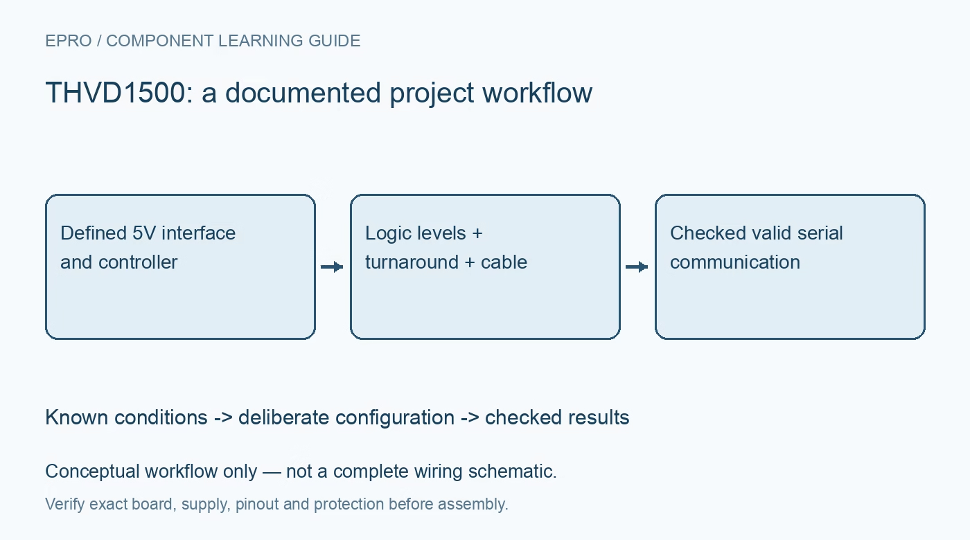
Use protected supplies and low-energy bench tests to assess requests, responses, missing nodes and permitted power cycles. Repeat at the intended baud rate with the actual cable and complete loading, logging errors and turnaround timing. Include controller resets to verify that the direction controls return to safe states. Preserve supply, controller voltage, cable topology and waveform captures with the results. A reliable short demonstration supports only that tested setup; it is not evidence of compliance or reliability across every possible network. Manufacturer documentation.
Related reading: THVD1419 RS-485 Transceiver: 7 Checks for Surge Claims and 250kbps Links.
Catalog note: The exact-part search did not return a matching Epro listing during preparation. Check the current catalog; this guide makes no price, availability or included-accessory claim.