


TLV3201 Comparator: 7 Checks for Push-Pull Threshold Timing

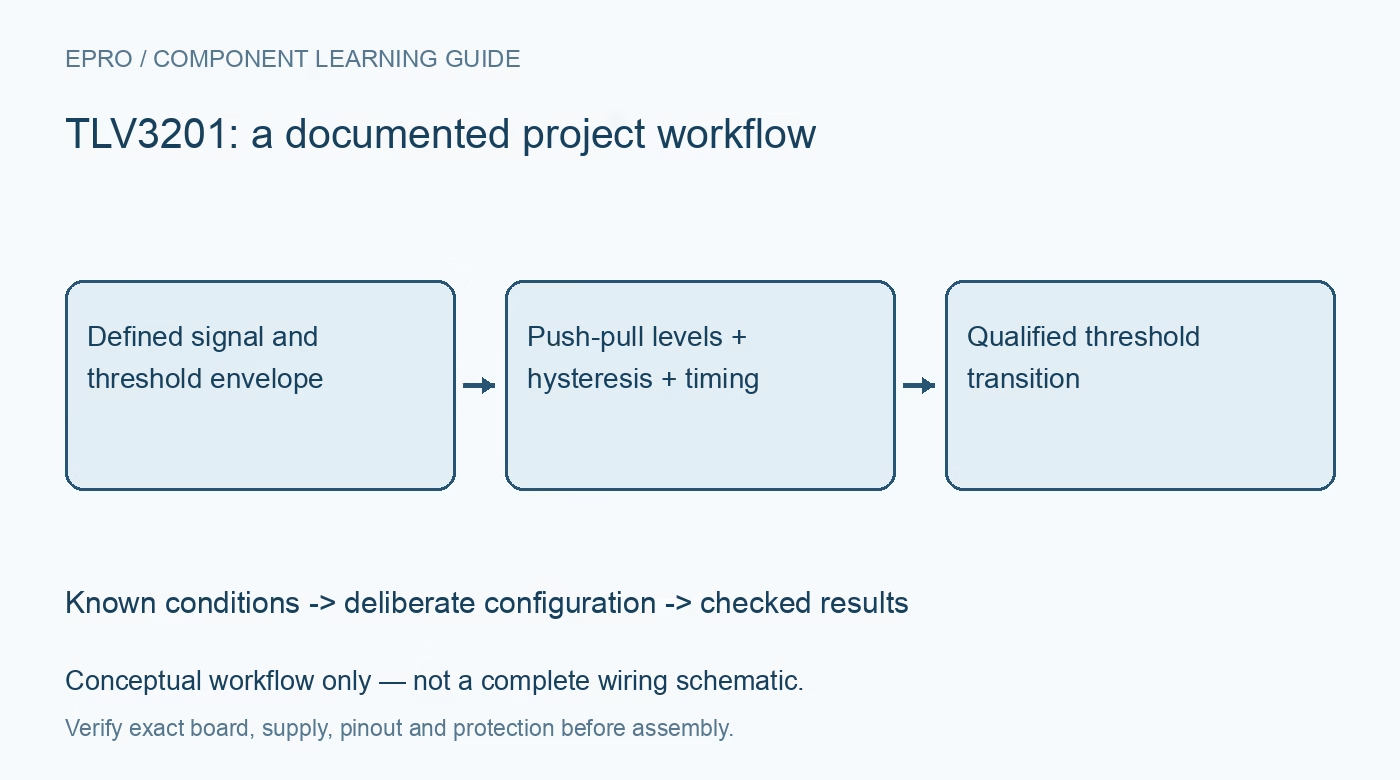
TLV3201 Comparator: 7 Checks for Push-Pull Threshold Timing
Plan TLV3201 threshold detection with seven checks for push-pull logic, input range, hysteresis, overdrive-dependent delay and startup behavior. This is a documentation-based planning guide, not a report of independent hands-on testing.
1. Use comparator behavior rather than op-amp assumptions
TLV3201 is a single comparator with a push-pull output; TLV3202 is the dual-channel relative. The specified supply range is 2.7 V to 5.5 V over the documented temperature range. A comparator decides which input is higher and changes logic state. It is not intended to be used as a linear voltage follower with ordinary negative feedback. Verify the package, input polarity and supply pins before replacing an operational amplifier or a superficially similar five-pin part. Manufacturer documentation.
2. Keep the output voltage domain compatible with the host
Unlike an open-collector comparator, TLV3201 actively drives both output states. There is no need for the output pull-up that is essential on an LM393-style open output, and a resistor cannot turn this device into an arbitrary higher-voltage open-drain translator. Check output high and low limits at the intended current and supply. A 5-V-powered comparator can overdrive a 3.3-V-only processor input. Do not connect its output directly to another active driver or a wired-OR interrupt line. Manufacturer documentation.
3. Treat common-mode extension as a specified small margin
The documented input common-mode range extends approximately 200 mV beyond the supply rails under its stated conditions. That is not general overvoltage tolerance or isolation. Internal protection diodes begin conducting outside their allowed region, and the manufacturer discusses current limiting for momentary faults. Absolute-maximum current limits are not normal operating targets. For external or noisy sources, design appropriate attenuation, protection and impedance so both input voltage and fault current remain controlled, including when the comparator supply is absent. Manufacturer documentation.
4. Budget threshold error and hysteresis separately
Actual switching depends on the reference level, comparator offset and hysteresis, as well as resistor and source errors. The device has internal hysteresis, but an application may need an external positive-feedback network to prevent chatter with a noisy or slowly moving signal. Use the documented topology for inverting or noninverting operation and calculate both rising and falling thresholds using actual output levels. A single nominal threshold number does not describe the complete transfer behavior. Manufacturer documentation.
Newest in the store


5. Do not interpret forty nanoseconds as a universal delay
The 40-nanosecond headline is tied to test conditions, including input overdrive and output loading. A signal barely beyond threshold or with a shallow slope can produce different timing and jitter. Propagation delay also does not include sensor response, reference filtering, processor synchronization or interrupt handling. Specify the smallest intended overdrive and load, then review the corresponding electrical data. Verify timing at the receiving circuit instead of treating a typical comparator figure as a guaranteed end-to-end response bound. Manufacturer documentation.
6. Control noise and feedback layout before adding capacitance
Place supply bypassing close to the device and keep input references away from output edges. Long feedback traces and high source impedance can couple a logic transition back into the threshold network. Adding capacitance may suppress noise but can also delay detection or change startup behavior; it is not a universal cure. Check the complete network with the intended source and cable configuration. Observe both inputs and output with an appropriate probe technique to distinguish genuine threshold crossings from measurement-induced ringing. Manufacturer documentation.
7. Validate startup and both crossing directions
Apply a bounded test signal and sweep through the threshold in both directions, recording the rising and falling trip levels. Repeat with the intended signal slope and output load. Check power-up, power-down and an absent input reference without assuming a defined comparator output below the specified supply range. If a transition triggers a consequential action, qualify it at the system level and provide the appropriate independent protection. Document threshold spread and timing conditions rather than claiming every crossing is detected at an exact voltage and delay. Manufacturer documentation.
Related reading: LM393 Comparator: 7 Pull-Up and Threshold Checks.
Catalog note: The exact-part search did not return a matching Epro listing during preparation. Check the current catalog; this guide makes no price, availability or included-accessory claim.