


TPS3808 Supervisor: 7 Checks for CT Delay and Reset Validity

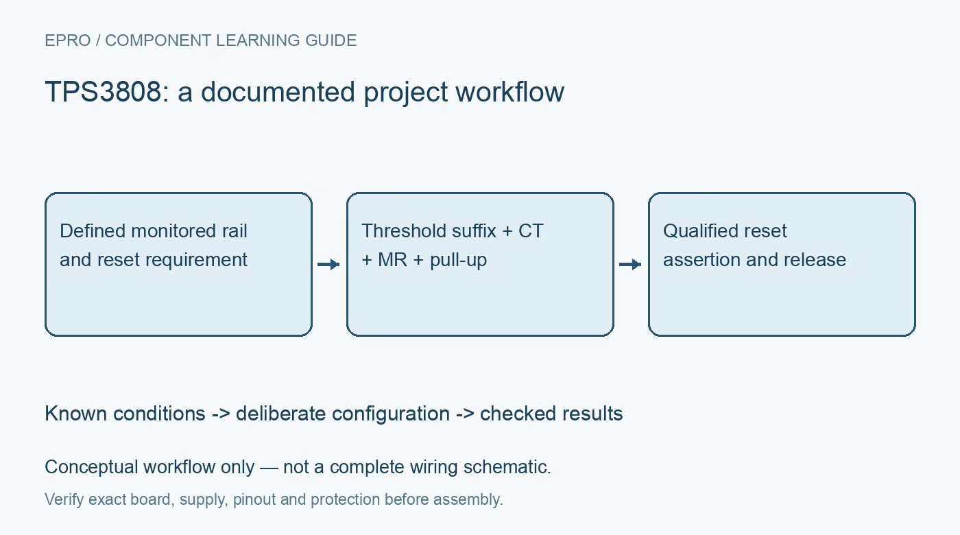
TPS3808 Supervisor: 7 Checks for CT Delay and Reset Validity
Plan TPS3808 supervision with seven checks for threshold suffixes, adjustable sensing, CT options, manual reset, pull-ups and low-supply validity. This is a documentation-based planning guide, not a report of independent hands-on testing.
1. Read the complete threshold and package code
TPS3808 is a supervisory family with fixed-threshold variants and an adjustable G01 option. A suffix associated with a standard rail does not simply mean the trip point equals that rail voltage. Check the ordering table and exact rising and falling threshold limits. Package pin assignments also differ between supported footprints, so verify the drawing before reuse. Define the minimum safe operating voltage of the protected processor separately; a supervisor can only enforce the threshold actually selected in the circuit. Manufacturer documentation.
2. Separate the supervisor supply from the monitored input
The recommended VDD operating range is 1.7 V to 6.5 V. SENSE is a separate input that can monitor a different rail within its documented limits. For G01, the nominal threshold is 0.405 V and an external divider scales a higher monitored voltage to that level. Calculate the rail threshold using both divider ratio and threshold tolerance, including input leakage and resistor tolerance. Monitoring a rail is not the same thing as regulating it or providing isolation from it. Manufacturer documentation.
3. Choose one of the three CT arrangements deliberately
Leaving CT open selects the nominal 20-millisecond reset-release delay. Connecting CT toward VDD through the specified 40-kilohm to 200-kilohm resistor selects the nominal 300-millisecond option. A ground-referenced capacitor provides a programmable delay instead. These configurations are not interchangeable, and CT should not be treated as a generic enable pin. Follow the current datasheet rather than shorting it directly to a rail based on a simplified summary. Include parasitic capacitance and board contamination in a high-impedance timing-node review. Manufacturer documentation.
4. Calculate capacitor delay with the documented units
For the capacitor option, the nominal relationship is CT in nanofarads = 175 multiplied by the quantity (delay in seconds minus 0.0005). A 0.1-second target gives approximately 17.4 nF before selecting a practical component. The datasheet requires at least 100 pF nominal for recognition of the capacitor mode. Use a low-leakage part, account for capacitance tolerance and effective value, and compare the expected delay range with the protected system requirement. A nominal calculation is not a guaranteed release time. Manufacturer documentation.
Newest in the store


5. Delay release rather than assuming every fault is filtered
RESET asserts when the monitored voltage is below threshold or MR is low. The selected timer delays deassertion after the required conditions become valid; it is not a general promise to ignore a brownout for that same interval. Short negative transients have their own overdrive-dependent response. Review the pulse-duration and threshold behavior for the intended rail noise. Excessive filtering on SENSE can delay detection of a genuine collapse, so validate the whole detection and release sequence. Manufacturer documentation.
6. Coordinate manual reset and the output pull-up
MR has an internal pull-up and can be left unused according to the documentation. If another device drives it, check voltage levels and possible current through that pull-up; an appropriate open-drain stage can avoid contention. RESET is also open drain and needs a compatible external pull-up and load. It is not a push-pull logic-high supply. Verify the receiver reset thresholds, sink current and release rise time, especially when the reset output is pulled to a different rail from VDD. Manufacturer documentation.
7. Do not rely on reset at arbitrarily low supply
Below the internal power-on-reset operating region, the device cannot guarantee that RESET remains driven low; the documentation identifies an undefined output region. A pull-up to a still-live rail can therefore create a misleading reset level while the supervisor is effectively unpowered. Analyze sequencing and add an appropriate system-level solution if a defined state is required there. Test source rise, brownout, MR assertion and repeated interruptions with a noncritical setup, recording actual threshold and release timing rather than assuming the nominal timer proves safe startup. Manufacturer documentation.
Related reading: TPS3890 Supervisor: 7 Checks for Sense and Reset Timing.
Catalog note: The exact-part search did not return a matching Epro listing during preparation. Check the current catalog; this guide makes no price, availability or included-accessory claim.