


TPS2120 Power Mux: 7 Checks for SEL Override and Status Ambiguity

TPS2120 Power Mux: 7 Checks for SEL Override and Status Ambiguity
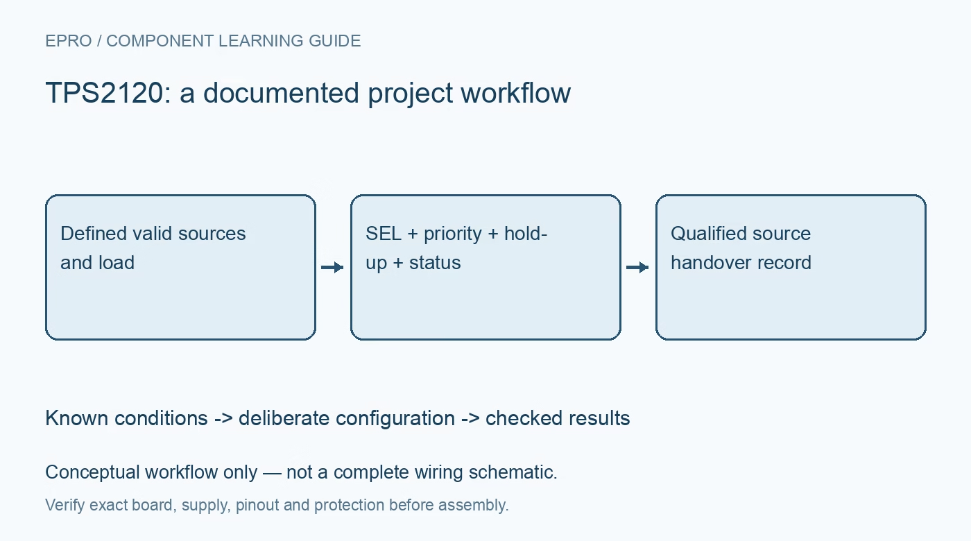
Plan TPS2120 source selection with exact SEL behavior, valid-input checks, current limits, hold-up capacitance and status interpretation. This is a documentation-based planning guide, not a report of independent hands-on testing.
1. Do not import TPS2121-only features
TPS2120 and TPS2121 share documentation but differ in package, interface and capabilities. TPS2120 has SEL rather than CP2, a different current-limit range and no basis for borrowing the TPS2121-specific fast-switchover headline. Identify the exact part and footprint before designing around a family application circuit. The recommended input operating range is 2.8V to 22V; the 24V absolute maximum is not a normal supply target. Include source tolerance and transients in the operating envelope. Manufacturer documentation.
2. Separate valid-source checks from priority
Selection depends first on whether each input passes the relevant undervoltage and overvoltage conditions. A preferred source that is invalid cannot be treated as an acceptable supply merely because firmware selected it. Configure OV1 and OV2 using their documented thresholds and tolerances, and define unused controls as instructed. Preserve the source-validity conditions beside the priority logic. Check startup, brownout and return-to-service behavior rather than evaluating the mux only with two ideal steady supplies. Manufacturer documentation.
3. Apply SEL override with the correct polarity
On TPS2120, SEL above the internal comparison threshold disables IN1 selection so a valid IN2 can supply the output. With SEL below threshold, selection still depends on PR1 and the valid-source conditions. It is not a symmetric two-state selector that always forces IN1 when low. The documented comparison threshold is approximately 1.06V typical. Review controller reset and pin-voltage limits before driving SEL. Test override and release with both higher and lower alternate-source voltages. Manufacturer documentation.
4. Distinguish priority mode from highest-voltage mode
When both sources are valid and PR1 is above its threshold, IN1 is prioritized. With PR1 below threshold and no overriding condition, the highest-voltage input is selected according to the documented behavior and hysteresis. Build a truth table for the actual resistor dividers and controller states, including tolerances. A source name such as main or backup does not establish its electrical priority. Confirm the intended selection when the source voltages cross, not just when one is completely disconnected. Manufacturer documentation.
Newest in the store


5. Read ST together with output voltage
The status signal is high for IN1 selection but is also high when both inputs are invalid and the output is high impedance. Therefore, a high ST value alone does not prove that the load is powered from IN1. A low state indicates IN2 under the documented valid operating conditions. Provide a compatible pullup and qualify status with input validity and actual output voltage. Preserve this ambiguity in firmware diagnostics rather than labeling every high indication as a healthy main supply. Manufacturer documentation.
6. Budget current limiting and output hold-up
TPS2120 has a documented adjustable current-limit range of 1A to 3A, distinct from the related part. Choose the programming resistor and load margin using the actual specifications and thermal conditions. Output capacitance and load determine droop during source handover; estimate capacitance from load current multiplied by the interruption interval divided by allowable droop, then validate the real waveform. Include startup inrush and source impedance. A seamless-switching family description is not a guarantee of zero voltage disturbance in every application. Manufacturer documentation.
7. Validate a complete handover matrix
Use protected supplies and a bounded load to test source removal, return, voltage crossing, SEL override, invalid inputs and controller reset. Capture IN1, IN2, OUT, SEL and ST where possible, recording current-limit and soft-start components with the setup. Verify downstream reset margins and temperature rather than accepting a visually continuous indicator light as proof of success. Keep measured handover behavior separate from manufacturer examples so the final record supports the exact source and load arrangement that was tested. Manufacturer documentation.
Related reading: TPS2121 Power Mux: 7 Checks for Deliberate Source Selection.
Catalog note: The exact-part search did not return a matching Epro listing during preparation. Check the current catalog; this guide makes no price, availability or included-accessory claim.