


TPS22919 Load Switch: 7 Checks for Smart ON and Output Discharge

TPS22919 Load Switch: 7 Checks for Smart ON and Output Discharge
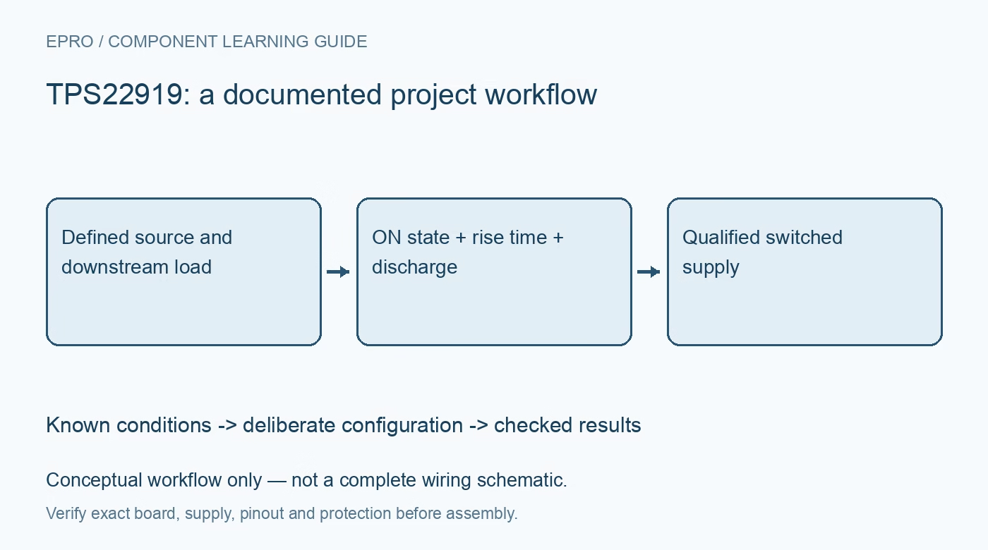
Plan TPS22919 switching with deliberate ON control, realistic current ratings, fixed slew behavior, output discharge and protected-load qualification. This is a documentation-based planning guide, not a report of independent hands-on testing.
1. Define the switch function and current envelope
TPS22919 is a single-channel load switch with controlled rise time and self-protection features, not a voltage regulator or a general programmable eFuse. Its recommended input range is 1.6 V to 5.5 V, with a maximum continuous-current rating of 1.5 A under applicable conditions. Check the actual board, package, load and thermal path. A short-circuit current figure is a protection parameter, not a larger continuous-current rating available for normal operation or an arbitrary charging load. Manufacturer documentation.
2. Give ON an explicit host-controlled state
The ON input controls the switch and must satisfy its documented logic thresholds. The smart pull-down is connected at low input levels and disconnected when ON is driven high to reduce unnecessary loss. Do not interpret this as a persistent command latch that makes a formerly enabled, subsequently floating host pin safe. Define reset, sleep and disconnected-host behavior in the external circuit. Where a downstream load must remain off, verify the physical startup state rather than relying solely on application firmware. Manufacturer documentation.
3. Distinguish controlled turn-on from adjustable ramp timing
The device provides controlled slew behavior with timing dependent on the documented operating conditions. It does not expose the same adjustable rise-time control arrangement as every other TPS229xx member. Use the appropriate timing tables and actual output capacitance to assess startup. Inrush depends on capacitance, voltage ramp and downstream activity, not just the no-load typical turn-on number. Check input droop and output rise together with a bounded source before enabling the real downstream module. Manufacturer documentation.
4. Budget on-resistance and package dissipation
On-resistance varies with input voltage and operating conditions, and the headline typical figure is not a guaranteed zero-loss connection. Estimate voltage drop and dissipation at the intended current, then assess the package and PCB thermal arrangement. The load’s lowest acceptable voltage matters, especially during startup or source droop. Measure voltage at the switched load, not only at VIN. A circuit can satisfy the switch’s nominal supply range while still delivering insufficient voltage to the downstream device. Manufacturer documentation.
Newest in the store


5. Connect QOD for the intended fall behavior
The quick-output-discharge arrangement controls how the switched output returns toward ground when disabled. Follow the documented QOD connection and any external resistance needed for the desired discharge behavior. Include output capacitance and downstream current paths when estimating fall time. Do not assume that driving ON low instantly removes stored energy or makes external signal pins harmless. Check that a separately powered cable or peripheral is not holding the output up or driving current through a discharge path unexpectedly. Manufacturer documentation.
6. Keep protection behavior separate from system fault clearance
The datasheet describes output-short current limiting and thermal shutdown with recovery behavior. These features protect the switch under specified conditions but do not establish complete protection for every connected load or wire. Investigate an unexpected current-limited or cycling rail instead of raising the source limit or repeatedly restarting it. Use safe, bounded qualification conditions and upstream protection. If the application needs reverse-current blocking or a particular fault-reporting policy, establish that capability explicitly rather than assuming it from the self-protected label. Manufacturer documentation.
7. Validate ordinary switching with the actual module
Test normal power-up, enable, disable, host reset and the intended restart interval with the downstream module attached under controlled conditions. Record source impedance, load current, output capacitance, ON levels and rise and fall behavior. Check that the module actually resets and releases external interfaces as intended; a partially discharged rail can defeat a supposed power cycle. This manufacturer-based checklist does not report independent load-switch tests. Revisit the evidence when changing the host power state, discharge network or downstream peripheral. Manufacturer documentation.
Related reading: TPS22965 Load Switch: 7 Checks for Bias, Inrush and Discharge.
Catalog note: The exact-part search did not return a matching Epro listing during preparation. Check the current catalog; this guide makes no price, availability or included-accessory claim.