


TPS7A4101 Regulator: 7 Checks for a 50-V Input Design

TPS7A4101 Regulator: 7 Checks for a 50-V Input Design
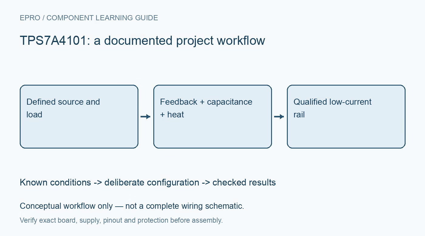
Plan TPS7A4101 supply limits, feedback, effective capacitance and thermal dissipation before using a high-input-voltage linear rail. This is a documentation-based planning guide, not a report of independent hands-on testing.
1. Establish the exact input and load envelope
The TPS7A4101 is a high-input-voltage linear regulator with a recommended input range of 7 V to 50 V and a maximum output-current capability of 50 mA subject to operating conditions. It is not an isolated supply and must not be treated as a direct mains interface. Define normal voltage, transients, load steps and ambient temperature before selecting components. Work on higher-voltage systems requires suitable expertise, equipment and enclosure design; a conceptual guide is not sufficient assembly instruction. Manufacturer documentation.
2. Keep pin ratings separate from the input headline
A fifty-volt input rating does not apply to every terminal. Read the pin-function, recommended-operation and absolute-maximum tables for the exact package. Review the enable connection and the feedback network independently, including what happens if a divider component opens or a controller loses power. Label the exposed thermal pad and ground arrangement in the board documentation. Avoid importing a convenient pin map from another regulator, even when the package and general application look familiar. Manufacturer documentation.
3. Calculate feedback with a realistic error budget
Use the manufacturer feedback equation to select an output voltage compatible with the source and required dropout margin. Include reference accuracy, resistor tolerance, temperature drift and feedback-input effects rather than presenting resistor arithmetic as guaranteed output accuracy. Consider divider power and voltage rating, especially when a large output voltage is intended. Keep the feedback route quiet and away from noisy currents. Document expected output limits at the load, not only a nominal value measured at the regulator pad. Manufacturer documentation.
4. Check effective capacitance at the operating voltage
The datasheet requires input capacitance of at least 1 µF and output capacitance of at least 4.7 µF under the relevant conditions. A ceramic capacitor’s marked value is not necessarily its effective value under DC bias, temperature and tolerance. Choose voltage ratings and packages with sufficient margin and place components according to the layout guidance. Review startup charging and load-step demands as well. An oversized catalog capacitance is not a substitute for confirming stability and actual capacitance on the intended rail. Manufacturer documentation.
Newest in the store


5. Make dissipation the main feasibility calculation
Approximate pass-device dissipation from the input-to-output drop multiplied by load current, then include other relevant losses. A 48-V source feeding a 5-V load at 20 mA already implies roughly 0.86 W in the pass path. That arithmetic is an illustration, not a safe rating for an arbitrary board. Check junction-temperature limits using the real copper area, airflow and enclosure. If the thermal budget fails, reduce the drop or change the power architecture rather than relying on thermal shutdown. Manufacturer documentation.
6. Review sequencing and stored energy before powering
Consider source removal, output capacitance, external backfeeding and every connection that can keep the load rail energized. Apply the datasheet guidance for reverse-voltage situations instead of assuming a linear regulator behaves like an ideal blocking diode. Define enable defaults and a safe load state during startup or shutdown. Keep any required protective circuitry rated for the actual energy and transient environment. Current limiting and thermal protection are fault responses, not authorization to operate continuously outside the recommended envelope. Manufacturer documentation.
7. Qualify the assembled rail without claiming isolation
Use an appropriately protected, current-limited test setup and qualified handling procedures. Check no-load and loaded voltage, startup, load transitions and stabilized package temperature across the intended supply range. Measure at both the regulator and load when wiring resistance matters. Record component choices, effective capacitance assumptions and thermal conditions with the results. A passing low-current test supports only the tested operating envelope; it does not establish mains safety, surge compliance, isolation or a universal fifty-milliamp capability at every input voltage. Manufacturer documentation.
Related reading: TPS7A4001 Regulator: 7 Checks Beyond Its 100 V Input Rating.
Catalog note: The exact-part search did not return a matching Epro listing during preparation. Check the current catalog; this guide makes no price, availability or included-accessory claim.