


Understanding ohm’s law

Understanding ohm’s law
Ohm’s law is one of the most useful ideas in basic electronics because it connects voltage, current, and resistance in a way you can calculate, test, and see in real circuits. Once you understand it, a series circuit stops looking like a mystery of wires and parts, and starts behaving like a predictable system. This guide explains the law clearly, then shows how it applies to resistors in series, voltage drop, total resistance, breadboard wiring, and simple circuit analysis.
What does Ohm’s law tell you?
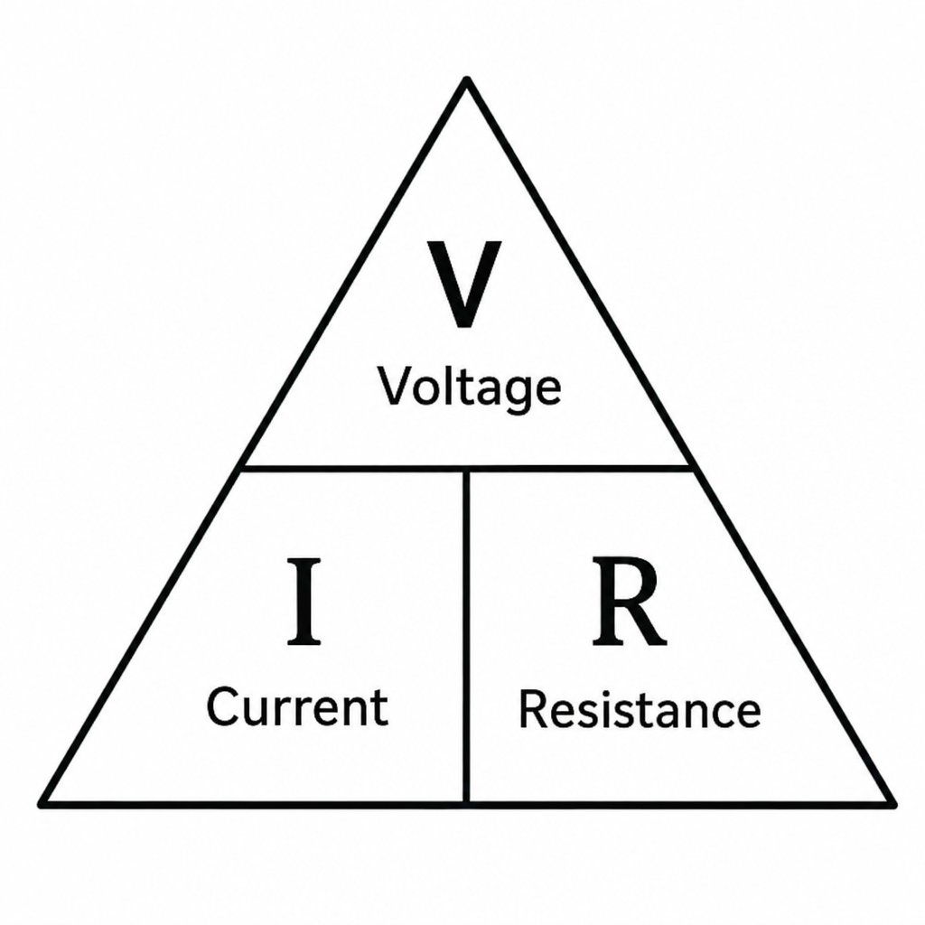
Ohm’s law tells you that current, voltage, and resistance are linked: current increases when voltage increases, and current decreases when resistance increases. In its most common form, it is written as V = I × R, where V is voltage in volts, I is current in amperes, and R is resistance in ohms. That simple relationship helps you estimate what will happen before you connect a battery, resistor, LED, sensor, or any other component.
In practical terms, voltage is the electrical “push,” current is the flow of electric charge, and resistance is the opposition to that flow. A higher voltage can push more current through a circuit, while a higher resistance limits current. If you know any two of the three values, you can calculate the third.
For example, if a 9-volt battery is connected to a 1,000-ohm resistor, the current is 9 ÷ 1,000, or 0.009 amps. That is 9 milliamps. This kind of quick calculation is the foundation for choosing safe resistor values, checking expected current, and understanding why components behave the way they do.

The three forms of Ohm’s law
Ohm’s law is flexible because the same relationship can be rearranged depending on what you need to find. You do not need to memorize a long list of formulas if you understand the relationship, but these three forms are helpful:
Voltage: V = I × R Use this when you know current and resistance and want to find the voltage across a component.
Current: I = V ÷ R Use this when you know voltage and resistance and want to find how much current flows.
Resistance: R = V ÷ I Use this when you know voltage and current and want to find the resistance needed.
These formulas are especially useful when working with resistor combinations. Whether you are looking at a single resistor, series resistors, resistors in series and parallel, or more complex resistor networks, Ohm’s law gives you a reliable way to reason through the circuit.
A common beginner mistake is to calculate with the wrong unit scale. Milliamps must be converted to amps before using the formula, and kilo-ohms must be converted to ohms. For example, 2.2 kΩ means 2,200 ohms, and 15 mA means 0.015 amps. Careful unit conversion prevents most calculation errors.
How a series circuit works
A series circuit has only one path for current to flow. The current leaves the power source, passes through each component one after another, and returns to the source. Because there is only one path, the same current flows through every component in the series circuit.
This is the key idea behind electrical series behavior. Components do not each “take” a different amount of current in a simple series path. Instead, they share the same current, while the supply voltage is divided across them according to their resistance.
When resistors are connected in series, their resistances add together. This combined value is called the total resistance. If you connect a 100 Ω resistor, a 220 Ω resistor, and a 330 Ω resistor in series, the total resistance is 650 Ω.
That total resistance determines the circuit current. If those same resistors are connected to a 9 V battery, the current is 9 ÷ 650, which is about 0.0138 amps, or 13.8 mA. Every resistor in that series chain carries the same 13.8 mA.
Resistors in series and total resistance
The simplest rule for resistors in series is that you add the resistor values:
- Rtotal = R1 + R2 + R3 + …
This makes series resistors easy to calculate, even when there are several parts. If three different resistors are connected in series to a battery, the total resistance is the sum of all three individual resistances. That total controls how much current the battery can push through the entire path.
Here are a few examples:
- 100 Ω + 100 Ω = 200 Ω total resistance
- 220 Ω + 470 Ω = 690 Ω total resistance
- 1 kΩ + 2.2 kΩ + 4.7 kΩ = 7.9 kΩ total resistance
- 330 Ω + 680 Ω + 1 kΩ + 2.2 kΩ = 4.21 kΩ total resistance
Adding resistance in series is useful when you do not have the exact resistor value you need. For example, if a circuit calls for about 1.5 kΩ and you have 1 kΩ and 470 Ω resistors available, placing them in series gives you 1.47 kΩ. That may be close enough for many basic projects, depending on tolerance and circuit requirements.
Series resistor combinations are also helpful for sharing voltage, limiting current, and creating simple reference points. In beginner electronics, they are often used to demonstrate current flow, calculate voltage drop, and show why the placement of components matters.
Why does voltage drop across each resistor?
Voltage drop happens because each resistor uses part of the supply voltage as current passes through it. In a series circuit, the individual voltage drops across all resistors add up to the source voltage. If the supply is 9 V, the drops across the series resistors must total 9 V, assuming the circuit is ideal and there are no other significant losses.
The size of each voltage drop depends on the resistor’s value. A larger resistor gets a larger share of the total voltage because the same current flows through every resistor, and Ohm’s law says V = I × R. With equal current, more resistance means more voltage drop.
Imagine a 9 V battery connected to 300 Ω and 600 Ω resistors in series. The total resistance is 900 Ω, so the current is 9 ÷ 900 = 0.01 A. The 300 Ω resistor drops 0.01 × 300 = 3 V, while the 600 Ω resistor drops 0.01 × 600 = 6 V. Together, the drops equal 9 V.
This is one of the most important patterns in circuit analysis. Current stays the same in a series path, but voltage divides according to resistance. Once that idea clicks, many resistor networks become much easier to understand.
A practical circuit analysis example
Let’s walk through a complete example using three resistors. Suppose a 12 V battery is connected to a 1 kΩ resistor, a 2 kΩ resistor, and a 3 kΩ resistor in series.
First, calculate the total resistance:
- Rtotal = 1,000 Ω + 2,000 Ω + 3,000 Ω
- Rtotal = 6,000 Ω
Next, calculate the current using Ohm’s law:
- I = V ÷ R
- I = 12 V ÷ 6,000 Ω
- I = 0.002 A, or 2 mA
Because this is a series circuit, the same 2 mA flows through all three resistors. Now calculate the voltage drop across each one:
- Across 1 kΩ: 0.002 A × 1,000 Ω = 2 V
- Across 2 kΩ: 0.002 A × 2,000 Ω = 4 V
- Across 3 kΩ: 0.002 A × 3,000 Ω = 6 V
The voltage drops are 2 V, 4 V, and 6 V. Added together, they equal 12 V, which confirms the calculation.
This process is a reliable way to analyze many basic circuits:
- Identify whether the components are in series, parallel, or a mixed arrangement.
- Find the total resistance for the section you are studying.
- Use Ohm’s law to calculate current.
- Use that current to calculate voltage drop across each series component.
- Check that the voltage drops add up to the source voltage.
That final check is important. If the math does not balance, there may be a unit error, an incorrect resistor value, or a misunderstanding of the circuit layout.
How do you connect resistors in series on a breadboard?
To connect resistors in series on a breadboard, place them end to end so the output leg of one resistor shares the same connected row as the input leg of the next resistor. The current must be forced to pass through each resistor in sequence, with no alternate path around any resistor. The open end of the first resistor connects toward the supply, and the open end of the last resistor connects toward the return side of the circuit.
Breadboards can confuse beginners because many holes are already connected underneath the plastic. On most solderless breadboards, the short rows in the center area are connected horizontally in groups, while the long power rails along the sides are connected vertically. If both legs of a resistor are placed in the same connected row, the resistor is effectively bypassed and will not behave as intended.Newest in the store


When building resistors in series on a breadboard, think in nodes. A node is a point where connected conductors share the same voltage. Two resistor legs that meet at a node are connected together, but that node should not accidentally connect to the supply rail or another unintended part of the circuit.
A simple breadboard layout might look like this in words:
- Connect the positive battery lead to the first resistor’s left leg.
- Put the first resistor’s right leg in a new row.
- Put the second resistor’s left leg in that same row.
- Put the second resistor’s right leg in another new row.
- Continue the pattern for additional resistors.
- Connect the final resistor’s free leg back to the battery’s negative side.
This is the basic method for how to connect resistors in series on a breadboard. If you are searching for resistors in series on breadboard examples, focus less on the physical appearance and more on whether the current has only one path through each resistor.

Common breadboard mistakes to avoid
Small wiring mistakes can completely change how a circuit behaves. Fortunately, most problems with resistors in series on a breadboard are easy to find once you know what to check.
Use this checklist before applying power:
- Check each resistor leg location. The two legs of the same resistor should not be in the same connected row.
- Confirm the shared row between resistors. One leg of the first resistor and one leg of the next resistor should share a row to create the series connection.
- Avoid accidental parallel paths. A jumper wire across a resistor can bypass it and reduce total resistance.
- Verify resistor values. Use the color bands, a multimeter, or labeled storage to confirm the resistor values before calculating.
- Check the power rails. Some breadboards have split rails, so a rail may not be continuous from one end to the other.
- Measure total resistance with power disconnected. A multimeter can confirm whether your series chain has the expected total resistance.
If your measured current is higher than expected, total resistance may be lower than your calculation. If no current flows, there may be an open connection. If one voltage drop is zero, that resistor might be shorted or not actually included in the current path.
Resistors in series and parallel behave differently
Resistors in series and parallel follow different rules because current paths are different. In series, there is one path, so the same current flows through every resistor and the resistance values add. In parallel, there are multiple paths, so the voltage across each branch is the same, while current divides between branches.
For series circuits:
- Total resistance increases as resistors are added.
- Current is the same through every resistor.
- Voltage is divided across the resistors.
- A break anywhere stops current through the whole path.
For parallel circuits:
- Total resistance decreases as branches are added.
- Voltage is the same across each branch.
- Current divides among the branches.
- One open branch may not stop current in the others.
This difference matters when analyzing resistor networks. A string of series resistors can be replaced by one equivalent resistance equal to their sum. Parallel groups require a different calculation, and mixed circuits often need to be simplified one section at a time.
The phrase resistors in series and parallel can describe a circuit that contains both types of connections. In that case, identify small groups first. Combine obvious series parts, combine obvious parallel parts, then repeat until the network becomes simple enough for Ohm’s law.
Simulations make Ohm’s law easier to see
Circuit simulations are useful because they let you change values, move wires, and observe the results without damaging parts. A tool such as a circuit construction kit can help students compare calculated current and voltage with simulated meter readings. This is why many learners look for resistors in series and parallel circuits using CCK simulation answers when practicing homework or lab activities.
The best way to use simulation answers is not to copy them, but to understand the pattern behind them. If you increase total resistance in a series circuit and keep voltage the same, current should go down. If you increase the source voltage and keep resistance the same, current should go up. If you make one resistor larger in a series chain, its voltage drop should become larger too.
Try this simple simulation exercise:
- Build a battery connected to one resistor.
- Measure current and voltage across the resistor.
- Add a second resistor in series.
- Measure current again and notice that it decreases.
- Measure the voltage drop across each resistor.
- Change one resistor value and watch how the voltage division changes.
This kind of experimentation reinforces the math. You are not just memorizing Ohm’s law; you are seeing it happen.
Resistor combinations in real projects
Resistor combinations appear in many everyday electronics projects. You might use a resistor to limit LED current, create a voltage divider, adjust a sensor signal, or build timing behavior with capacitors. Understanding series and parallel behavior helps you choose parts confidently instead of relying on guesswork.
Series resistors are useful when you need a resistance value that is not available as a single part. They are also useful when distributing voltage across multiple components. However, every resistor has a power rating, so voltage and current calculations matter. If a resistor must dissipate too much power, it can heat up or fail.
Power can be calculated with P = V × I, or by using related forms such as P = I² × R. For beginner circuits using small batteries and common resistors, power may not always be a major issue, but it should never be ignored. A resistor that is safe in one circuit may be unsuitable in another with higher voltage or current.
Resistor networks can also be used to create precise relationships between voltages. A voltage divider, for example, uses two resistors in series with an output taken from the point between them. The output voltage depends on the ratio of the two resistor values. This is useful, but the divider can behave differently when connected to a load, so real circuits may require extra analysis.
Resistors and capacitors in series and parallel
Many circuits include more than resistors. Resistors and capacitors in series and parallel are common in filters, timing circuits, signal coupling, and power supply smoothing. While resistors oppose current in a steady, predictable way, capacitors store and release electrical energy.
In a DC circuit, a capacitor initially allows changing current as it charges, then eventually behaves more like an open circuit once fully charged. A resistor in series with a capacitor controls how quickly that capacitor charges or discharges. This timing behavior is described by the RC time constant, based on resistance and capacitance.
Parallel capacitors add in a direct way, while series capacitors follow a reciprocal rule similar in shape to parallel resistor calculations. That can feel confusing at first because resistor and capacitor combinations do not always use the same rules. The important point is to identify the component type and connection style before choosing the formula.
For beginners, it is best to master resistor series and parallel calculations first. Once those are comfortable, adding capacitors becomes less intimidating because the same habits still apply: identify nodes, trace current paths, simplify sections, and check whether your answer makes physical sense.
Practical tips for learning circuit analysis
Circuit analysis becomes easier with a repeatable process. Instead of staring at a diagram and guessing, break it down into smaller observations.
Use these habits when solving Ohm’s law problems:
- Redraw messy circuits. A cleaner diagram often reveals which parts are truly in series or parallel.
- Label known values. Write voltage, resistance, and current values directly near the components.
- Mark current paths. Follow the path from the source through the circuit and back again.
- Look for nodes. Components connected between the same two nodes are often in parallel.
- Simplify step by step. Replace simple resistor combinations with equivalent resistance values.
- Keep units visible. Write Ω, kΩ, A, mA, V, and W so unit mistakes stand out.
- Check your answer. Ask whether the current, voltage drop, and total resistance make sense.
A good rule of thumb is that adding resistors in series increases total resistance, which lowers current if voltage stays the same. Adding resistors in parallel decreases total resistance, which increases total current from the source if voltage stays the same. These simple expectations help you catch errors before they become confusing.
A simple way to remember the big ideas
Ohm’s law is not just a formula. It is a way of thinking about cause and effect in a circuit. Voltage pushes, resistance limits, and current responds.
For a series circuit, remember these essentials:
- Current is the same everywhere in the series path.
- Total resistance is the sum of all series resistor values.
- Voltage drop is larger across larger resistors.
- All voltage drops add up to the source voltage.
- A break anywhere in the path stops the whole series circuit.
For resistors in series and parallel, remember that the structure determines the rule. Do not choose a formula just because there are multiple resistors. First ask whether the current has one path or more than one path. That single question often points you in the right direction.
Final takeaway
Understanding Ohm’s law gives you a practical foundation for building and troubleshooting circuits. Once you can calculate current, total resistance, and voltage drop, series resistors and basic resistor networks become much easier to work with. Whether you are wiring resistors in series on a breadboard, comparing series and parallel behavior in a simulation, or analyzing a real project, the same core relationship keeps guiding the work: voltage, current, and resistance are connected.