


Understanding variable resistor symbol

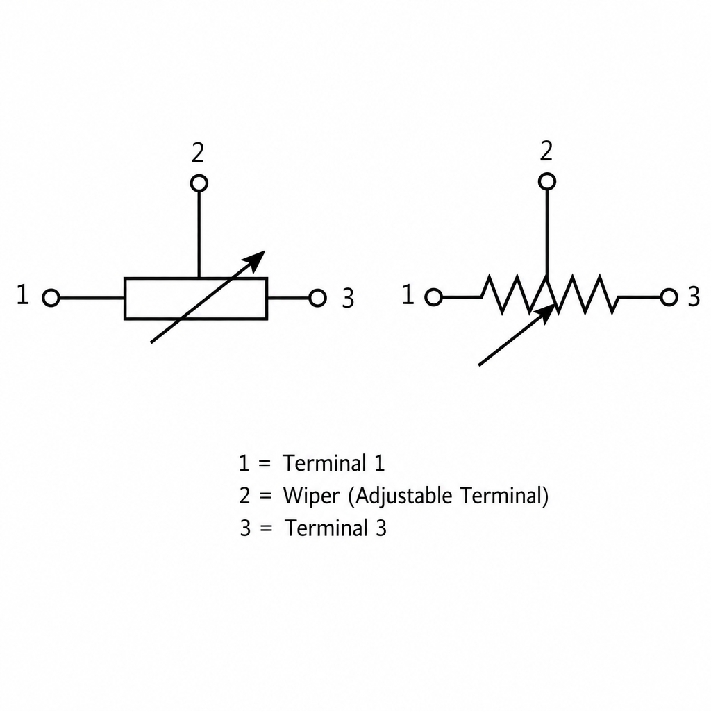
Understanding variable resistor symbol
A variable resistor symbol shows a resistor whose value can be adjusted, usually by adding an arrow across or toward the standard resistor shape. Once you understand how it differs from the fixed resistor symbol, schematic drawings become much easier to read, build, and troubleshoot. This guide explains the most common resistor notation styles, what each mark means, and how to recognize a variable resistor in a circuit diagram.
What does the variable resistor symbol mean?
The variable resistor symbol means the resistance in that part of the circuit can be changed instead of staying at one set value. In most schematics, it starts with the normal resistor symbol and adds a diagonal arrow, which represents adjustment. That adjustment may be made by a knob, slider, screw, sensor-linked mechanism, or another control depending on the component and circuit.
In practical terms, the symbol tells you that the circuit designer expects resistance to vary. That variation may control brightness, volume, timing, motor speed, signal level, calibration, or another electrical behavior. The exact function depends on how the component is connected, but the visual clue is the same: the resistor is not fixed.

The basic resistor symbol comes first
Before reading a variable resistor symbol, it helps to understand the basic resistor symbol. A resistor limits or controls current flow in a circuit, and the schematic symbol is a simplified drawing used instead of a realistic resistor image. This lets engineers, technicians, students, and hobbyists understand the electrical function without seeing the physical component.
There are two common visual styles for a standard resistor symbol. One uses a zigzag line, which is common in many North American drawings. The other uses a small rectangle, which is common in IEC-style schematics. Both represent the same idea: a fixed amount of resistance placed between two circuit points.
The symbol of a fixed resistor does not usually include an arrow, adjustment mark, or moving contact. It is simply the resistor shape with a lead on each side. In a schematic, the label beside it often includes a reference designator such as “R1” and a resistance value such as “10 kΩ.”
Fixed and variable symbols are related
A variable resistor is best understood as an adjustable version of the fixed resistor symbol. The fixed resistor symbol shows a set resistance value, while the variable version shows resistance that can be changed within a range. This is why the variable symbol is drawn by modifying the standard resistor symbol instead of inventing a completely unrelated icon.
The most common difference is the arrow. If you see a diagonal arrow crossing a zigzag or rectangle resistor, the drawing is usually showing a variable resistor or adjustable resistor. If the arrow points to the resistor body but does not show a third terminal, the symbol may indicate a two-terminal variable resistor, often used as a rheostat.
A potentiometer is closely related but usually has three terminals. In a resistor diagram, the third terminal is often drawn as a wiper arrow touching the resistor element. That wiper divides the total resistance into two parts and lets the circuit use a variable voltage or signal level.
How is the symbol of a fixed resistor different?
The symbol of a fixed resistor is different because it shows no adjustment, no wiper, and no arrow. It represents a component with a single resistance value chosen during resistor design, manufacturing, or circuit selection. When you see the symbol for fixed resistor in a schematic, you should assume the value stays constant under normal circuit use unless the notes say otherwise.
A fixed resistor symbol is usually used for current limiting, voltage division, pull-up or pull-down connections, biasing, filtering, and protection. Its value may still change slightly with temperature or tolerance, but that is not the intended control action. By contrast, the variable resistor symbol tells the reader that adjustment is part of the circuit’s purpose.
This distinction matters when assembling or repairing a circuit. Replacing a variable component with a fixed one can remove the ability to calibrate or control the circuit. Replacing a fixed component with an adjustable one may also change reliability, repeatability, or safety if the circuit was not designed for adjustment.
Common forms of variable resistor notation
Resistor notation is the set of labels, symbols, values, and abbreviations used to describe resistors in a circuit. It can include the schematic shape, the reference designator, the resistance value, and sometimes the component type. Understanding this notation helps you move from symbol recognition to practical circuit interpretation.
Common variable resistor notation includes:
- R or VR reference labels: A fixed resistor may be labeled R1, R2, or R3. A variable resistor may be labeled VR1, RV1, or sometimes simply R with a note showing that it is adjustable.
- Resistance value or range: A symbol might be marked 10 kΩ, 100 kΩ, or 1 MΩ. For a variable part, that value often indicates the maximum resistance across the full element.
- Potentiometer labels: A potentiometer may be marked POT, VR, or RV, depending on the drawing style.
- Adjustment notes: Some schematics add words such as trim, adjust, gain, balance, offset, volume, or calibration to show what the control does.
- Terminal numbering: Potentiometers may show three terminals. The outer terminals connect to the resistive element, while the center terminal is usually the wiper.
This notation is especially helpful when a schematic contains several adjustable parts. A variable resistor symbol circuit can look simple, but the surrounding labels tell you whether the part controls user input, factory calibration, feedback, or signal scaling.
Potentiometer and rheostat symbols
Two components commonly shown with variable resistor symbols are potentiometers and rheostats. They both use adjustable resistance, but they are not used in exactly the same way. Recognizing the difference helps you understand the circuit’s intent.
A potentiometer is typically a three-terminal device. It acts as an adjustable voltage divider, with the wiper moving along a resistive path. You may see this in audio volume controls, analog input controls, sensor calibration circuits, and signal level adjustments.
A rheostat is typically used as a two-terminal variable resistor. It changes the amount of resistance in series with a load. You may see it in current-control applications, though modern circuits often use more efficient electronic control methods instead of high-power rheostats.
A trimmer or preset resistor is a small adjustable resistor used for calibration rather than frequent user control. Its symbol may look like a variable resistor, but the component on the board is usually adjusted with a small screwdriver. In documentation, a note near the symbol often explains what should be adjusted and when.
Why resistor symbols matter in real schematics
A resistor schematic is more than a collection of icons. It is a map of electrical behavior. The resistor symbol electrical designers choose tells the reader whether resistance is fixed, variable, tapped, temperature-dependent, light-dependent, or part of a more complex network.
If you misread the resistor representation, you may misunderstand how the circuit works. For example, a potentiometer connected between supply voltage and ground with its wiper feeding another stage is likely acting as an adjustable voltage source. The same symbol connected with only two terminals may be acting as a variable series resistance.
This is also why schematic symbols are intentionally simple. A realistic resistor illustration may show colored bands, metal leads, a ceramic body, or a plastic control shaft. A schematic symbol ignores all of that and focuses on function. The drawing asks, “What does this part do electrically?” rather than “What does this part look like physically?”
A practical checklist for reading resistor symbols
When you encounter a resistor icon or unfamiliar symbol in a circuit drawing, slow down and read it in context. The mark itself is important, but the surrounding connections often confirm the meaning.Newest in the store


Use this quick checklist:
- Identify the base shape. Is it a zigzag line or a rectangle? Either one may be a resistor symbol.
- Look for an arrow. A diagonal arrow usually means adjustable resistance. A wiper arrow touching the resistor element often suggests a potentiometer.
- Count the terminals. Two terminals usually suggest fixed resistance or rheostat-style use. Three terminals usually suggest a potentiometer.
- Read the label. Reference labels such as R, VR, RV, or POT provide useful clues.
- Check the value. A value like 50 kΩ near a variable symbol usually indicates the available resistance range.
- Follow the connections. A component in series with a load behaves differently from one wired as a voltage divider.
- Read nearby notes. Words like gain, offset, trim, volume, or speed explain the design purpose.
This simple process prevents many common mistakes. It is especially useful when working from older drawings, mixed symbol standards, or diagrams created by different software tools.

The role of symbols in resistor design
Resistor design involves more than selecting a resistance value. Designers must think about tolerance, power rating, temperature behavior, adjustment range, physical size, mounting style, and how the component will be used. The schematic symbol does not show every one of these details, but it helps communicate the most important electrical role.
For a fixed resistor, the symbol says the circuit needs a stable resistance at that location. The exact part may then be chosen based on value, wattage, accuracy, and operating conditions. For a variable resistor, the symbol says the circuit needs a controlled change in resistance or voltage division.
The schematic may also separate electrical design from physical layout. A small resistor image in a catalog can help identify the part visually, but the schematic symbol helps explain how it functions. Later, a circuit board layout or assembly drawing shows where the physical component sits.
What should you watch for when using a variable resistor?
When using a variable resistor, watch for terminal choice, resistance range, power rating, adjustment direction, and whether the circuit needs a two-terminal or three-terminal connection. The symbol gives you the starting point, but the datasheet, circuit notes, and application determine the correct installation. A potentiometer wired incorrectly may still fit physically while behaving backward or failing to provide the expected output.
One common issue is confusing the wiper with an end terminal. In a potentiometer, the wiper is the moving contact, and its voltage or resistance changes as the shaft or slider moves. If you connect to the wrong terminals, the control may work in reverse, stay fixed, or create an unstable signal.
Another concern is using an adjustable resistor where too much current flows. A small trimmer may be fine for calibration in a signal circuit but unsuitable for controlling a high-current load. The schematic symbol may not show the power rating, so the component specification remains important.
Reading a resistor diagram with confidence
A resistor diagram becomes easier to read when you combine three clues: symbol shape, labels, and circuit context. The shape tells you the general component type. The label tells you how the designer named it. The connections tell you how it behaves in the circuit.
For example, a rectangle with two leads and the label R5 is probably a fixed resistor. A zigzag with a diagonal arrow and the label VR1 is probably an adjustable resistor. A resistor element with three terminals and a wiper is likely a potentiometer, especially if it is connected between two voltage points.
This layered reading approach also helps when different standards appear in the same project. You may see the fixed resistor symbol as a zigzag in one drawing and a rectangle in another. Instead of focusing only on the drawing style, focus on the electrical meaning.
Symbol, image, and illustration are not the same
It is easy to mix up a resistor symbol, resistor image, and resistor illustration, but each serves a different purpose. A symbol is used in schematics to show electrical function. An image shows the physical component. An illustration may simplify the part for teaching, labeling, or documentation.
A resistor representation in a schematic is intentionally abstract. It does not tell you the body color, exact size, brand, or lead shape. Instead, it shows where resistance exists in the circuit and whether it is fixed or adjustable.
A product photo or realistic resistor illustration is useful when identifying parts on a bench. A schematic symbol is more useful when tracing current paths, analyzing voltage drops, or understanding control behavior. Good technical communication often uses both, but it uses them for different jobs.
Common mistakes to avoid
Even experienced readers can misinterpret resistor symbols if a drawing is crowded or unfamiliar. The most common mistakes are simple, but they can lead to wrong parts, incorrect wiring, or confusing test results.
Avoid these errors:
- Assuming every resistor symbol means a fixed part. An arrow changes the meaning.
- Ignoring the third terminal. A potentiometer is not just a two-lead resistor when all three terminals are used.
- Confusing schematic orientation with physical orientation. A symbol can be rotated or mirrored without changing the basic function.
- Treating the schematic as a parts photo. The symbol does not show the actual package or adjustment style.
- Skipping notes near the symbol. Calibration labels often explain why the component is adjustable.
- Using only the icon without checking the value. The same symbol can represent many resistance ranges.
The best habit is to verify both the symbol and the circuit role before choosing or connecting a part. That extra moment can save a lot of troubleshooting later.
A simple way to remember the meaning
Think of the fixed resistor symbol as a steady restriction and the variable resistor symbol as an adjustable restriction. The base resistor shape tells you resistance is present. The arrow tells you someone or something can change it.
For a potentiometer, think of the arrow as a movable pickup point along the resistor. For a rheostat, think of it as changing how much resistance the current must pass through. These mental models make resistor symbol meaning easier to remember than memorizing drawings alone.
Once you learn the fixed resistor symbol, the symbol for fixed resistor, and the adjustable variations, most schematics become far less intimidating. You can identify where current is being limited, where voltage is being divided, and where a circuit is designed to be tuned.
Key takeaway
The variable resistor symbol is a modified resistor symbol that shows adjustable resistance, most often with an arrow or wiper mark. The symbol of a fixed resistor shows a set resistance value, while variable versions show that resistance or output can be changed. By reading the base shape, arrow, terminals, labels, and surrounding connections, you can understand resistor notation clearly and interpret a resistor schematic with more confidence.