


Common Mistakes When Using SMD Resistors

Common Mistakes When Using SMD Resistors
SMD resistors make modern electronics smaller, cleaner, and easier to assemble at scale, but they also leave less room for error than many through-hole parts. Choosing the wrong size, value, tolerance, voltage rating, or footprint can create heat problems, assembly defects, unreliable readings, or premature failure. This guide walks through the most common mistakes engineers, buyers, technicians, and hobbyists make with surface mount resistors so you can design, source, and install them with more confidence.
What goes wrong most often with SMD resistors?
Most problems with SMD resistors come from treating them as simple interchangeable parts instead of precision components with mechanical, electrical, and assembly constraints. A resistor may look correct in the bill of materials, but if the package is too small, the power rating is too low, the footprint is mismatched, or the voltage stress is ignored, the circuit can behave unpredictably. The best results come from checking the complete set of smd resistor specifications before layout, purchasing, and assembly.
This is especially important because chip smd resistors are compact by design. Their small body size is useful in dense PCBs, but that compact form also limits heat dissipation and can make markings harder to read. A mistake that would be obvious on a larger component may be nearly invisible on a tiny 0402 or 0201 package.
Choosing the wrong SMD resistor size
One of the easiest mistakes is selecting a package based only on available board space. Smaller is not always better. SMD resistor sizes affect power handling, voltage capability, solderability, inspection, and rework difficulty.
For example, a very small package may fit neatly between IC pins, but it may not handle the heat produced by the circuit. A larger package may take more room, but it can be easier to assemble, inspect, and replace. When comparing sizes of smd resistors, consider the entire use case, not just the footprint on the PCB.
Common size-related problems include:
- Choosing a package too small for the required power dissipation.
- Using a tiny part where manual soldering or rework is expected.
- Copying a footprint from another design without checking the actual component dimensions.
- Ignoring assembly house recommendations for minimum package size.
- Selecting a part that fits the schematic but not the manufacturing process.
A practical approach is to start with the electrical requirements, then confirm the package can support manufacturing and long-term reliability. If the board has enough space, choosing a slightly larger package can often reduce risk.

Ignoring power and heat dissipation
Power rating is one of the most misunderstood smd resistor ratings. A resistor may have the correct resistance value and tolerance, yet still fail because it is asked to dissipate more heat than its body and PCB environment can handle.
The basic power relationship is simple: power increases with current and voltage stress. In practice, though, real boards add complications. Copper area, airflow, nearby hot components, ambient temperature, and enclosure design all affect how hot the part becomes. A resistor that works on an open test bench may run too hot inside a compact enclosure.
To reduce heat-related failures, check these points before committing to a design:
- Calculate expected power dissipation under normal and worst-case conditions.
- Compare that number with the resistor’s rated power, including derating guidance where applicable.
- Consider the board environment, not just the datasheet rating.
- Keep heat-sensitive components away from resistors that may run warm.
- Use multiple resistors in series or parallel when spreading power improves reliability.
Heat problems can also shift resistance over time. Even if the resistor does not fail outright, excessive temperature can reduce accuracy and shorten service life.
Overlooking voltage limits
Many designers check resistance and wattage but forget voltage rating. This is a serious issue in dividers, snubbers, sensing circuits, power supplies, lighting drivers, and industrial controls. High voltage smd resistors exist for a reason: standard chip resistors may not be appropriate when the voltage across the component is high, even if power dissipation appears acceptable.
Voltage stress can cause instability, arcing risk, surface contamination sensitivity, or long-term degradation. The smaller the package, the more carefully creepage, clearance, and rated voltage should be reviewed. This is one area where assuming “the resistor value is correct, so it is fine” can lead to costly reliability issues.
When a circuit involves elevated voltage, review the resistor’s maximum working voltage and overload voltage, then compare those numbers with the real operating conditions. Also confirm that the PCB layout supports the voltage environment. Component selection and board spacing need to work together.
Are the listed SMD resistor values always suitable?
No. SMD resistor values must be evaluated with tolerance, temperature coefficient, circuit function, and availability in mind. A nominal value may look correct in a schematic, but the final circuit can drift or perform poorly if the tolerance is too wide or the value is difficult to source consistently.
This matters in feedback networks, sensor conditioning, current sensing, timing circuits, and precision analog stages. A 1% part may be acceptable in many general applications, while precision measurement circuits may require tighter tolerance and a lower temperature coefficient. On the other hand, using an unnecessarily precise resistor in a noncritical pull-up circuit can increase cost without improving performance.
Common value-selection mistakes include:
- Choosing a nominal value without checking tolerance impact.
- Mixing series values without considering production availability.
- Forgetting that temperature changes can alter resistance.
- Using precision parts where general-purpose resistors would be adequate.
- Using general-purpose parts where precision or stability is required.
The goal is not to choose the most expensive component. It is to choose the value and tolerance that match the job the resistor is doing.
Misreading markings and part numbers
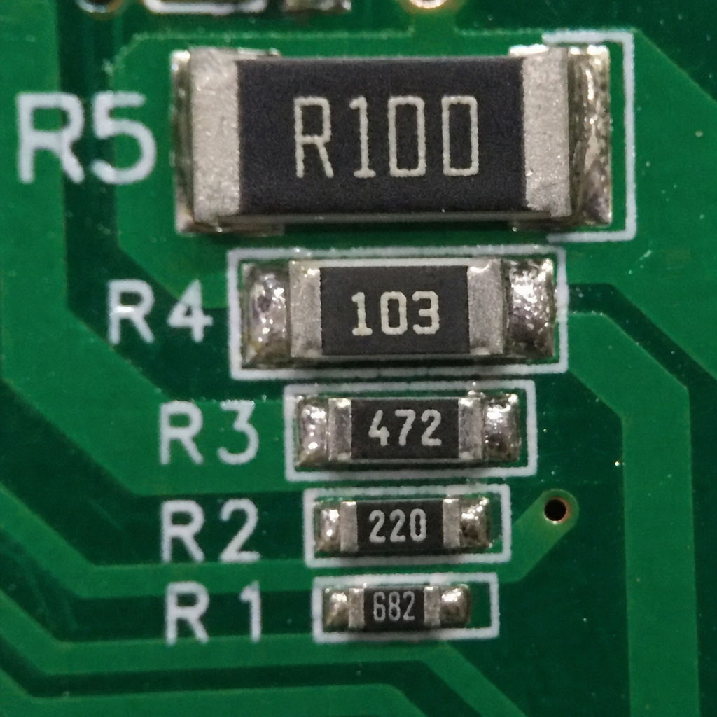
Larger smd chip resistors may carry printed markings, but small packages often have limited or no markings at all. Even when codes are present, they can be easy to misread under poor lighting or magnification. This creates risk during prototyping, repair, inspection, and inventory handling.
Part numbers can also be confusing because manufacturers encode package size, resistance value, tolerance, temperature coefficient, packaging method, and series information in different ways. Two parts may share the same resistance value but have different ratings or construction. That difference may matter in high-frequency, high-voltage, precision, or current-sense applications.
A safer workflow is to verify components from the reel label, purchase documentation, and datasheet rather than relying only on visual identification. For hand assembly, keep parts separated, labeled, and protected from mix-ups. It is much easier to prevent a reel or bag error than to diagnose dozens of incorrectly placed resistors later.
Treating all SMD resistor types as the same
There are several smd resistor types, and they are not interchangeable in every circuit. Thick film resistors are common and cost-effective for many general uses. Thin film resistors are often preferred where accuracy, stability, and lower noise are important. Current sense resistors are designed for low resistance values and power handling. Arrays and networks can save space and improve matching in some designs.
The best type depends on the electrical role of the component. A pull-down resistor, LED current limiter, voltage divider, and precision gain-setting resistor all have different priorities. Using the same default component everywhere may simplify the BOM, but it can also compromise performance.
Newest in the store


Consider the application before choosing:
- General digital pull-ups and pull-downs often prioritize availability and cost.
- Analog signal paths may need better tolerance, stability, and noise performance.
- Current sensing may require low resistance, suitable power rating, and low temperature drift.
- High-voltage circuits may require specialized construction and appropriate spacing.
- Compact modules may benefit from resistor arrays when matching and density matter.
Matching smd resistor applications to the correct construction helps avoid both overdesign and underdesign.
Using the wrong footprint or land pattern
A correct component on the wrong footprint is still a design problem. If pads are too large, too small, uneven, or incorrectly spaced, soldering defects become more likely. Parts may tombstone, skew, bridge, or form weak joints. These issues can be especially frustrating because the schematic and BOM may both appear correct.
Footprint mistakes often happen when designers copy land patterns from older libraries without checking the exact part series. Even parts with the same imperial size code can have slightly different recommended pad dimensions. Manufacturing process also matters: reflow soldering, wave soldering, and hand soldering can each influence the preferred pad design.
Before releasing a board, confirm that the footprint matches the selected part and the assembly process. If possible, use manufacturer-recommended land patterns and review them with your assembler. A few minutes spent checking the PCB library can prevent hard-to-find failures after assembly.
Buying only by price or availability
When you buy smd resistors, it is tempting to filter by resistance value and price, then choose the first available option. That approach can work for noncritical prototypes, but it is risky for production or demanding designs. The lowest-cost part may have different tolerance, temperature behavior, packaging, voltage rating, or long-term availability than expected.
Catalog searches can also be inconsistent. Some suppliers use terms like resistors smd, surface mount resistors, chip resistors, or smd chip resistors for similar product categories. The naming may vary, but the responsibility is the same: confirm the full specification before ordering.
A reliable purchasing checklist should include:
- Resistance value and tolerance.
- Package size and footprint compatibility.
- Power rating and voltage rating.
- Temperature coefficient and operating temperature range.
- Resistor type or technology.
- Packaging format, such as cut tape, reel, or tray.
- Manufacturer part number and approved alternatives.
- Stock continuity for future builds.
For production, document acceptable substitutes clearly. A substitute should match the critical smd resistor specifications, not just the ohmic value.
Skipping derating in real operating conditions
Datasheet ratings are usually based on defined test conditions. Real products may face higher ambient temperatures, limited airflow, vibration, contamination, or continuous operation. Derating means using a component below its maximum limits to improve reliability.
Skipping derating is common when a design works during initial testing. The board powers up, measurements look acceptable, and the resistor seems fine. But long-term operation can expose marginal decisions, especially near heat sources or inside sealed housings.
Good derating practice is not guesswork. It starts with identifying the worst-case electrical load and environmental conditions. From there, choose a resistor with enough margin that normal variation, aging, and temperature do not push it beyond safe operation.
Forgetting parasitic effects in sensitive circuits
At low frequencies and moderate values, resistors can often be treated as simple ideal components. In fast, sensitive, or high-impedance circuits, the physical package and construction can matter more. Parasitic capacitance, inductance, noise, and voltage coefficient may affect circuit behavior.
This is particularly relevant in RF designs, precision analog front ends, high-speed signals, and measurement equipment. A resistor that is perfectly acceptable in a logic pull-up may not perform the same way in a low-noise amplifier or high-frequency termination. The selected package size, layout, and resistor technology can all influence performance.
To avoid surprises, review application notes, evaluate layout carefully, and test the circuit under realistic conditions. If the resistor sits in a critical signal path, treat it as part of the system, not as an afterthought.
Poor storage, handling, and assembly practices
SMD resistors are durable in many ways, but poor handling can still create problems. Contamination, mixed parts, mechanical damage, and soldering stress can all affect assembly quality. Very small packages are especially easy to lose, flip, or place incorrectly.
During assembly, excessive heat or repeated rework may damage pads or stress components. Manual soldering can be effective, but it requires the right tip, temperature, flux, and technique. For small packages, magnification and good lighting are not optional luxuries; they are practical quality tools.
Good handling habits include:
- Keeping reels, strips, and bags clearly labeled.
- Avoiding unnecessary mixing of similar-looking values.
- Using proper ESD and cleanliness practices where required by the assembly environment.
- Inspecting solder joints under magnification.
- Limiting rework cycles when pads or components show signs of stress.
Small process improvements often prevent large debugging headaches.
A practical pre-design checklist
Before finalizing a PCB or placing an order, pause and review the resistor choice as a complete engineering decision. This checklist can help catch common issues early:
- Does the resistance value support the circuit function across tolerance limits?
- Is the selected package appropriate for power, voltage, assembly, and rework?
- Have you checked both power rating and maximum working voltage?
- Is the resistor technology suitable for the application?
- Does the PCB footprint match the exact component series?
- Are temperature coefficient and operating temperature acceptable?
- Is there enough design margin for worst-case conditions?
- Are approved alternates documented for purchasing?
- Can the assembler reliably place and inspect the chosen size?
- Are critical components easy to identify during prototyping and repair?
This process does not need to slow the design down. In most cases, it saves time by reducing redesigns, sourcing surprises, and intermittent failures.
The takeaway for better SMD resistor decisions
SMD resistors are simple in concept, but successful use depends on more than choosing an ohmic value. Size, rating, voltage, tolerance, resistor type, footprint, sourcing, and operating environment all influence performance and reliability. The smaller and more demanding the circuit, the more important these details become.
If you are designing a new board, reviewing a BOM, or preparing to buy smd resistors, take time to check the complete specification rather than relying on assumptions. Careful selection of surface mount resistors leads to cleaner layouts, fewer assembly issues, and more dependable electronics in the field.