


Understanding Resistance Units Concepts

Understanding Resistance Units Concepts
Electrical resistance is one of the core ideas behind every working circuit, from a small LED project to the electrical systems used in vehicles, buildings, factories, and aircraft. Once you understand resistance units, the electrical resistance formula, and the practical steps for measuring resistance, circuit behavior becomes much easier to predict. This guide explains the essentials in plain language, with useful examples you can apply when reading diagrams, choosing components, or testing electrical resistance safely.
What does electrical resistance mean?
Electrical resistance is the opposition a material or component gives to the flow of electric current. In simple terms, current wants to move through a circuit, and resistance controls how easily that movement happens. A low-resistance path allows current to flow more freely, while a high-resistance path limits current and can convert electrical energy into heat.
The standard unit of electrical resistance is the ohm, represented by the Greek letter omega: Ω. If you have ever seen “10 Ω,” “1 kΩ,” or “2.2 MΩ” printed on a schematic or component package, those labels describe resistance units. For anyone solving a unit of electrical resistance crossword clue, the answer is almost always “ohm.”
Resistance matters because it shapes how circuits behave. It helps set current levels, divide voltage, protect sensitive parts, control signals, and produce useful heat. Without resistance, most circuits would either fail immediately or become impossible to control.

Resistance units in everyday circuit language
Resistance units are usually written in ohms, but real circuits often use values that are much smaller or much larger than one ohm. That is why prefixes are common.
Common ways you will see resistance written include:
- Ω, or ohm: The base unit of resistance.
- mΩ, or milliohm: One-thousandth of an ohm, often used for very low-resistance connections, conductors, contacts, and shunts.
- kΩ, or kilo-ohm: One thousand ohms, common in signal circuits, pull-up resistors, and basic electronics.
- MΩ, or mega-ohm: One million ohms, often used in insulation, leakage testing, sensors, and high-impedance circuits.
The scale matters. A 1 Ω resistor behaves very differently from a 1 MΩ resistor. The first may allow a relatively large current, depending on voltage and power rating. The second may allow only a tiny current in the same conditions. Understanding the unit prefix prevents costly mistakes, especially when replacing components or interpreting a technical drawing.
Ohm’s law explained in practical terms
Ohm’s law explains the relationship between voltage, current, and resistance. The most common electrical resistance formula is:
R = V / I
In this formula, R is resistance in ohms, V is voltage in volts, and I is current in amperes. The same relationship can also be rearranged as V = I × R or I = V / R, depending on what you need to find.
Here is the practical meaning: if voltage stays the same and resistance increases, current decreases. If resistance decreases, current increases. This is why adding resistance can protect an LED, limit current in a control circuit, or change the behavior of a sensor input.
For example, imagine a simple circuit with a 12-volt supply and a 6 Ω load. Using Ohm’s law, the current is 12 divided by 6, or 2 amps. If the resistance changes to 12 Ω, the current becomes 1 amp. Nothing mysterious is happening; the resistance is simply restricting current flow more strongly.
Why does resistance in circuits matter?
Resistance in circuits matters because it determines how much current flows, how voltage is distributed, and how much heat may be produced. Every conductor, switch, connector, resistor, heating element, and human touch point has some level of resistance. Even when a wire is described as a good conductor, it is not resistance-free.
In a working circuit, resistance can be intentional or unwanted. Intentional resistance is designed into the circuit to perform a function. Unwanted resistance may come from corrosion, loose terminals, damaged cables, worn contacts, poor crimps, or overheated components. A small increase in resistance at the wrong point can cause voltage drop, unreliable operation, or excess heat.
This is why technicians take resistance readings when troubleshooting. Measuring resistance can reveal open circuits, short circuits, degraded connections, and components that have drifted outside their expected range. It can also confirm whether a replacement part matches the required value before it is installed.
Factors affecting resistance
The factors affecting resistance are mostly related to material, size, temperature, and condition. When you understand these variables, resistance readings make more sense and become easier to interpret.
Key factors include:
- Material: Copper has low resistance and is widely used for wiring. Rubber, glass, and many plastics have high resistance and are used as insulators.
- Length: Longer conductors usually have more resistance because current must travel farther through the material.
- Cross-sectional area: Thicker conductors usually have lower resistance because current has more space to flow.
- Temperature: Many metals increase in resistance as temperature rises, while some other materials behave differently.
- Connection quality: Loose, dirty, corroded, or oxidized connections can add resistance even when the wire itself is sound.
- Physical damage: Crushed cables, cracked components, and overheated terminals can change resistance in unpredictable ways.
These factors explain why the same circuit may perform differently under load, after long use, or in harsh environments. In practical work, resistance is not just a number on a meter; it is a clue about the physical condition of the electrical path.
Resistance and conductivity work together
Resistance and conductivity describe opposite sides of the same idea. Resistance tells you how much a material opposes current flow. Conductivity tells you how well a material allows current to flow. A highly conductive material usually has low resistance, while a poor conductor usually has high resistance.
This relationship is important when choosing materials. A power cable should have low resistance so it can carry current efficiently. An insulating sleeve should have high resistance so current does not escape the intended path. A sensor element may be designed so its resistance changes with temperature, pressure, light, or strain.
Thinking in terms of resistance and conductivity helps you move beyond memorizing formulas. It encourages better questions: Is this part supposed to conduct? Is it supposed to insulate? Has its resistance changed because of heat, damage, moisture, or contamination?
Newest in the store


Common types of resistors
Resistors are components designed to provide a specific amount of resistance. They appear in power supplies, control boards, communication circuits, lighting systems, instruments, and countless electronic devices. Different types of resistors are used because circuits have different requirements for accuracy, power handling, size, stability, and adjustability.
Common types of resistors include:
- Fixed resistors: Provide one stated resistance value and are widely used for current limiting and voltage division.
- Variable resistors: Allow resistance to be adjusted, often through a knob, screw, or sliding contact.
- Potentiometers: A common variable resistor used for controls such as volume, position, or calibration.
- Thermistors: Change resistance with temperature and are often used for sensing or protection.
- Photoresistors: Change resistance with light exposure and may be used in simple light-detection circuits.
- Power resistors: Built to dissipate more heat than small signal resistors.
- Precision resistors: Designed for tighter tolerance where accurate resistance values are important.
Choosing a resistor is not only about ohms. You also need to consider tolerance, power rating, temperature behavior, physical package, and the environment where the resistor will operate.
How do you measure electrical resistance with a multimeter?
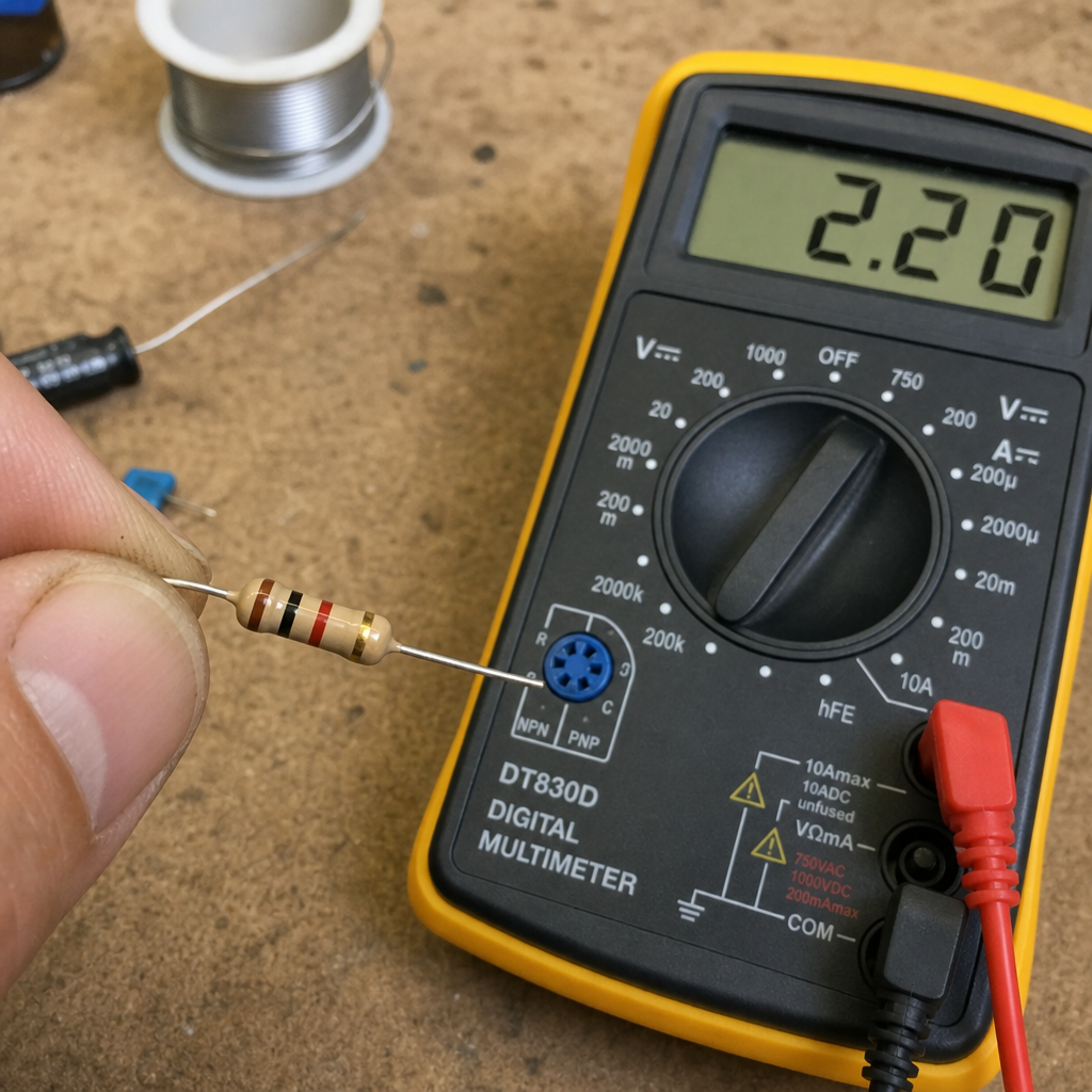
To answer how to measure electrical resistance with multimeter equipment: set the meter to the resistance or Ω range, isolate the component or circuit from power, place the probes across the part being tested, and read the displayed value. The circuit must not be energized while measuring resistance, because the meter applies its own small test signal. Live voltage can damage the meter, distort the reading, or create a safety hazard.
A basic process for measuring resistance is:
- Turn off power completely. Disconnect the circuit from its supply and verify it is safe.
- Discharge stored energy. Capacitors can hold charge after power is removed, so follow safe discharge procedures where needed.
- Select the resistance function. Use the Ω symbol on the multimeter. If the meter is not auto-ranging, choose a range higher than the expected value.
- Isolate the component if necessary. Other connected parts can create parallel paths and change the reading.
- Touch the probes to both ends. Good probe contact matters, especially with low-resistance measurements.
- Read and interpret the value. Compare it with the expected resistance, tolerance, or service information.
When testing electrical resistance, remember that “OL,” “overload,” or a similar display usually means the resistance is higher than the selected range or the circuit is open. A reading near zero may indicate a short circuit or a very low-resistance path. Context is everything, so compare the measurement with what the circuit is supposed to do.
Measuring resistance accurately
Measuring resistance sounds simple, but accuracy depends on technique. Your hands, probe pressure, lead resistance, surface contamination, and connected components can all influence the result. This is especially true when measuring very low resistance or very high resistance.
Use these practical habits:
- Zero or compensate for test leads when measuring low resistance, if your meter supports it.
- Avoid touching metal probe tips during high-resistance measurements, because your body can create a parallel path.
- Clean test points if corrosion, paint, oil, or oxidation could affect contact.
- Compare against a known-good value whenever possible instead of relying on one isolated reading.
- Check the meter battery and fuse if readings seem unstable or impossible.
- Measure out of circuit when nearby components could influence the result.
For precision work, specialized methods may be needed. A four-wire, or Kelvin, measurement can reduce the effect of lead and contact resistance. Insulation resistance testing may require a dedicated insulation tester rather than a standard handheld multimeter. The right tool depends on the resistance range and the safety requirements of the system.
Electrical resistance heating and useful heat
Electrical resistance heating happens when current flows through a resistive material and electrical energy is converted into heat. This principle appears in heaters, toasters, heated seats, defrosters, industrial processes, and many temperature-control systems. In these applications, resistance is not a problem; it is the feature doing the work.
The amount of heat depends on voltage, current, resistance, time, and the design of the heating element. A heating element must be built to withstand its operating temperature without failing, deforming, or creating unsafe conditions. It also needs proper insulation, spacing, control, and protection.
Unplanned resistance heating is different. A loose terminal, overloaded connector, or damaged conductor can heat up because resistance is concentrated at a weak point. This can lead to equipment failure or fire risk. That is why warm plugs, discolored terminals, melted insulation, and burning smells should always be treated seriously.
Electrical resistance in safety and specialized applications
Electrical resistance is not limited to circuit boards and components. It also plays an important role in personal protective equipment, coatings, materials, and safety testing.
The electrical resistance of human body tissue varies widely based on skin condition, moisture, contact area, voltage, and the current path through the body. Dry skin may provide more resistance than wet or broken skin, but relying on body resistance for protection is never safe. Electrical safety depends on proper design, insulation, grounding, protective devices, procedures, and training.
Safety shoes electrical resistance is another practical example. Some footwear is designed to reduce electric shock risk by providing insulation, while other footwear is designed to control static discharge in sensitive environments. The intended use matters, so footwear should be selected according to the hazard, workplace rules, and applicable product information.
Specialized industries may also use engineered materials such as aerospace electrical resistance coating. In aviation and aerospace contexts, coatings and conductive or resistive surface treatments may help manage static, protect surfaces, support sensing functions, or contribute to system performance. Because these applications are highly specific, product selection and testing should follow the relevant engineering requirements rather than general assumptions.
A practical checklist for working with resistance
Before you measure, select, or troubleshoot anything related to resistance, slow down and confirm the basics. A careful approach prevents bad readings and unsafe decisions.
Use this checklist:
- Identify the expected value. Look for markings, schematics, service information, or design notes.
- Confirm the unit. Check whether the value is in Ω, mΩ, kΩ, or MΩ.
- Remove power before resistance testing. Do not measure resistance on a live circuit.
- Consider parallel paths. Connected components can make a good part look faulty.
- Account for temperature. Some resistance values change noticeably when components are hot or cold.
- Inspect before measuring. Burn marks, corrosion, loose hardware, or cracked insulation may explain the problem.
- Use the right meter and range. A standard multimeter is useful, but not ideal for every resistance test.
- Think about safety. High-energy systems, capacitors, batteries, and industrial equipment may require formal procedures.
This checklist is simple, but it reflects how experienced technicians think. They do not treat a number as the whole answer. They combine the reading with circuit knowledge, visual inspection, safety awareness, and the expected behavior of the equipment.
Key takeaways
Resistance controls current, shapes voltage behavior, and often determines whether a circuit works safely and reliably. The ohm is the base unit, but practical work often involves milliohms, kilo-ohms, and mega-ohms. Ohm’s law connects resistance, voltage, and current, making it one of the most useful tools in electrical troubleshooting.
Good resistance work is part math, part measurement, and part judgment. Know the expected value, use the correct resistance units, understand the factors affecting resistance, and measure with the circuit safely de-energized. Whether you are learning electronics, maintaining equipment, comparing types of resistors, or investigating a fault, a clear grasp of electrical resistance gives you a stronger foundation for every circuit decision that follows.