


74HC165 Shift Register: Eight Inputs, Not Eight LED Outputs

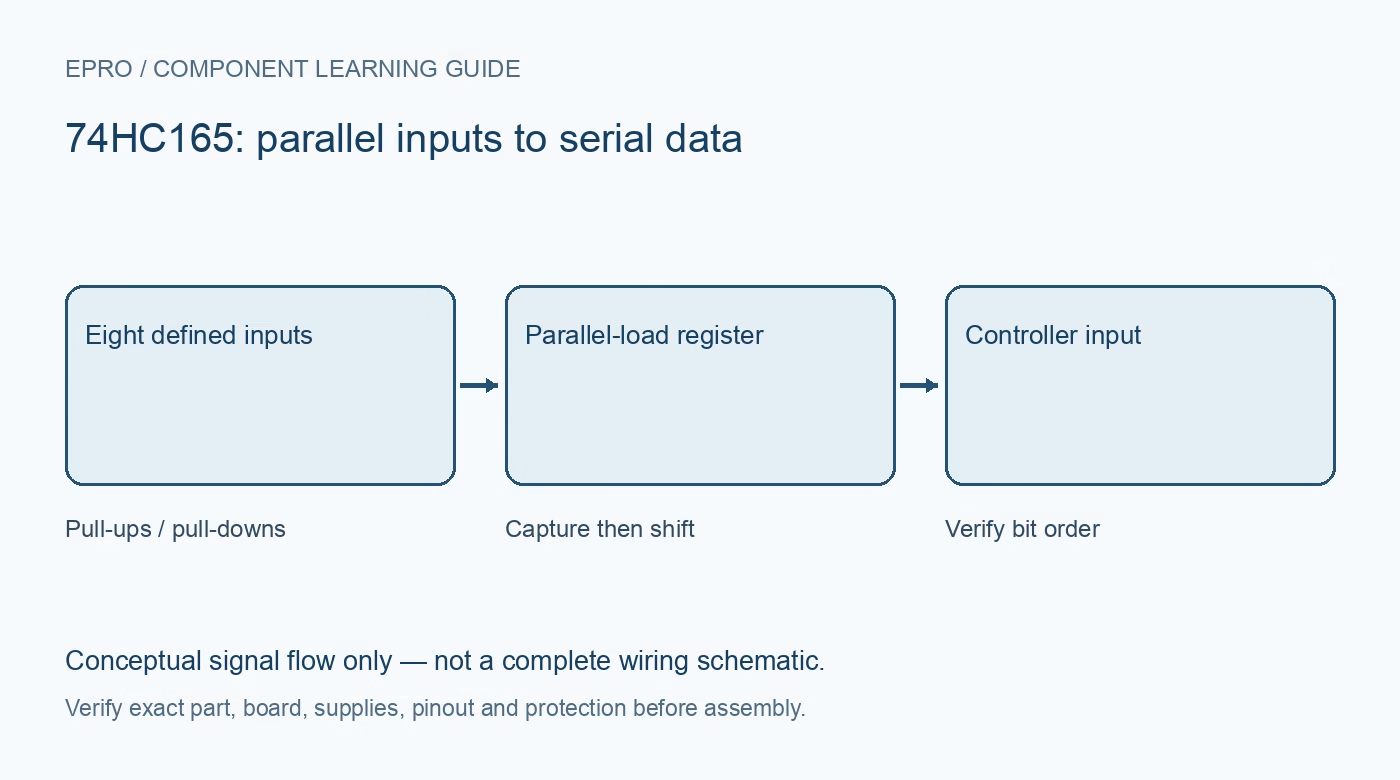
The 74HC165 captures parallel input states and shifts them out serially. It is useful for reading switches when controller pins are limited, but it is not the same kind of expansion as a 74HC595 output register. Understand load, clock and input biasing before choosing the circuit.
Choose the correct direction of conversion
The 165 is parallel-in/serial-out: eight external logic states can be captured and read through a serial output. The 595 commonly used for LEDs is serial-in/parallel-out. Similar package size and related part numbers do not make them drop-in substitutes. A 165 input also does not provide analog conversion or arbitrary voltage protection.
Read load and clock controls together
In the Nexperia reference, pulling parallel-load PL low loads D0–D7 asynchronously. With PL high and clock enable CE low, rising clock edges shift the captured data. A high CE inhibits clocking. Respect setup, hold and recovery timing, and avoid changing CE carelessly around a clock edge because it also participates in the clock-control logic.
Give every input a defined state
Open switches need suitable pull-up or pull-down resistors so their associated inputs do not float. Define the serial input and control inputs as well, even when a function is not otherwise used. A randomly changing serial result can come from an unconnected input rather than a defective chip. Pull-up choices must suit leakage, wiring and noise conditions.
Check HC versus HCT thresholds
The exact logic family matters. The referenced documentation distinguishes CMOS-level HC inputs from TTL-level HCT inputs and provides different operating specifications. Do not power an HC part at 5 V and assume any 3.3 V controller output meets its guaranteed high threshold. Likewise, the serial output voltage must be safe for the receiving controller.
Capture first, then decode the bits
Use a known pattern to establish which external input appears first and whether the normal or complementary serial output is connected. A library may label bits in a different order from a physical row of switches. Record the mapping instead of reversing wires until the displayed binary number happens to look familiar.
Plan expansion and debounce separately
Registers can be cascaded using the documented serial path, but verify chain order, timing and wiring quality before adding more devices. Capturing a switch state does not remove mechanical bounce. Debounce or event filtering belongs in the application logic, with a sampling policy appropriate to the interface. This expansion is for low-voltage logic, not direct industrial field inputs.Newest in the store


Availability and illustration note
No matching product was found in the checked Epro catalog for this topic on 19 October 2026. This article therefore does not quote an Epro price or claim stock. The original illustration shows conceptual signal flow only, not a complete circuit or a photograph of a supplied product. Obtain a documented component or carrier with a known pinout and electrical specification.
Frequently asked questions
Can 74HC165 replace a 74HC595 LED driver directly?
No. Their normal conversion directions and control functions differ.
Does a parallel capture debounce a push button?
No. It captures the electrical state at that moment; mechanical debounce still needs an appropriate application strategy.
Related Epro reading
Review breadboard connections before assembling a prototype. For controller expansion, the Mega 2560 pin guide explains why pin names and electrical limits must be checked together.
Technical references and test limitations
This guide uses the documentation linked below. The procedures are for a controlled, low-voltage learning setup; no independent hands-on test of the particular seller board is claimed. Record the actual part markings, wiring and firmware version before drawing conclusions from a test.