


74HC4050 Arduino: 7 Polarity and Logic-Load Checks

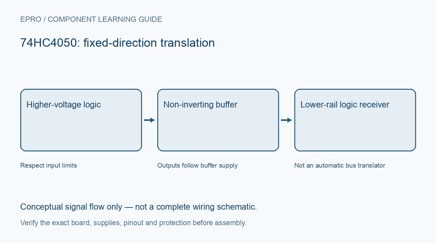
A 74HC4050 Arduino test should verify static logic levels before attempting a high-speed peripheral. Use the exact buffer documentation and a compatible logic load, keeping its fixed direction and supply-referenced outputs clear throughout the setup.
Draw the signal direction first
Identify which device transmits each signal and which receives it. Route only the intended source into the buffer input and the receiver from its output. A fixed non-inverting channel cannot automatically reverse direction when a shared data line changes ownership.
Verify rails and common reference
Check the buffer supply against the desired output logic level and the selected part’s recommended range. Connect the appropriate reference ground and local decoupling. Input overvoltage tolerance does not permit an excessive buffer supply or make every connected host pin equally tolerant.
Check a single channel without a peripheral
Use one known safe host output and a high-impedance logic measurement or compatible input. Confirm the exact package’s input and output pins with power disconnected. Do not connect two driven outputs together or use a bare LED as an unreviewed output-current test.
Verify low and high without inversion
Drive a steady low, then a steady high, and confirm the buffer output follows the same logical state at its own supply-referenced level. Measure against valid thresholds, not an assumption that an unloaded voltage will remain identical under every load or temperature.
Define unused channels and reset states
Bias unused inputs to valid levels and keep unused outputs unconnected. Consider what the real signal source does during reset, because an unconfigured host pin can float before application code starts. Do not assume the buffer provides a global enable pin or automatic safe shutdown.
Move to timing tests deliberately
After the static check, use a modest supported clock rate and inspect the actual receiver response. Include delay and edge quality in its timing budget. A successful slow transaction does not prove reliable operation at the peripheral’s maximum clock frequency or across long breadboard wiring.
Newest in the store


Review power sequence before final connection
Check the exact device’s powered and unpowered conditions and the receiving board’s limits before tying together separate supplies. Perform rewiring only with power removed. This demonstration validates a limited logic path; it does not provide safety isolation, analog scaling or an independent guarantee of a peripheral’s correct operation.
Frequently asked questions
Should the output invert a high input?
No. The 74HC4050 channels are non-inverting.
Can it be used unchanged for an automatically reversing data line?
No. The fixed direction must match the complete interface design.
Availability and illustration note
No matching Epro product was returned by the catalog search on 21 October 2026 UTC. This learning guide does not assert stock, a selling price or compatibility of an unidentified substitute. The illustration is an original conceptual signal-flow diagram, not a product photograph or complete wiring schematic.
Related Epro reading
For a first bench setup, review breadboard connections and continuity checks and I2C voltage-level translation. These guides do not replace the exact module schematic.
Technical references and limitations
Source: Nexperia 74HC4050 datasheet. Electrical limits apply to the named part, not automatically to every carrier board. This is a documentation-based learning workflow, not a claim of independent hardware testing, traceable calibration or safety certification.