


ESP32 Pinout: 9 GPIO Checks for Safer Wiring

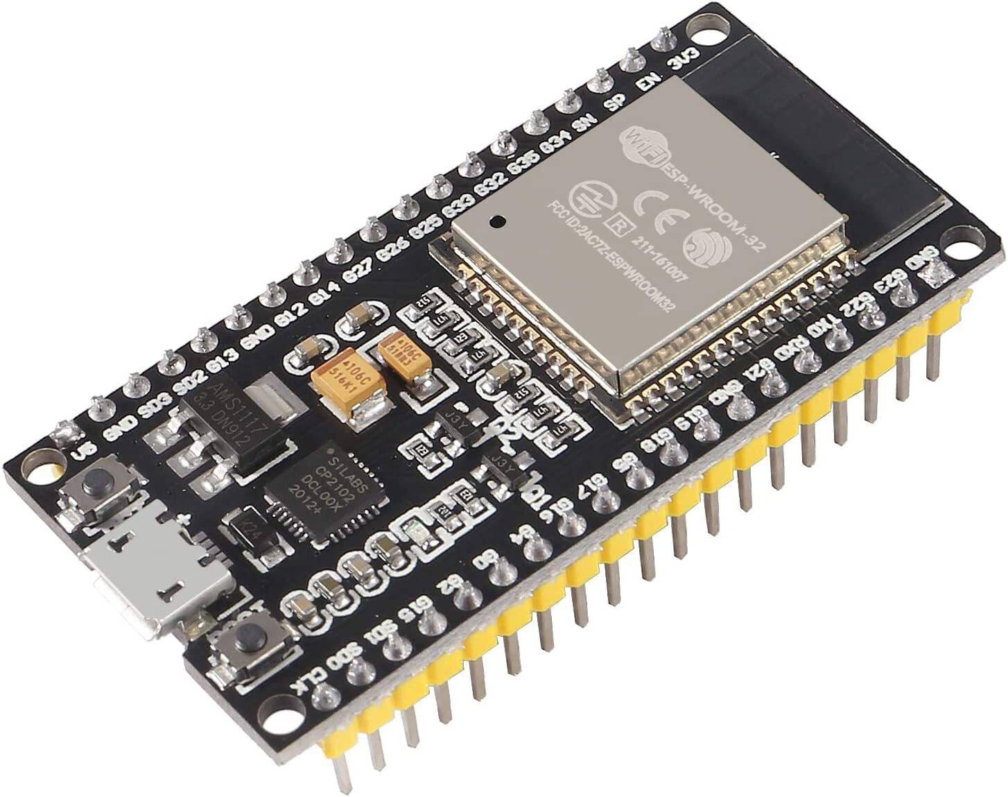
Last checked: 18 October 2026. Product prices and availability, where shown, are a snapshot of Epro listings checked on this date. Confirm the live listing before ordering.
An ESP32 pinout is useful only when it matches your exact board and chip family. This guide covers the original ESP32 family commonly found on ESP32-WROOM development boards. It is not a pin map for ESP32-C3, ESP32-S2, ESP32-S3 or every camera board.

For physical header positions, use the labels printed on your board and its manufacturer’s diagram. Never count across an online photograph without checking board orientation. The same module can appear on development boards with different header layouts.
ESP32 pinout: quick reference for common signals
| Signal or pin group | Practical check |
|---|---|
| 3V3 and GND | Regulated 3.3V rail and circuit reference; verify available current. |
| 5V or VIN | Board-specific power connection, not a 5V-tolerant GPIO. |
| GPIO34–39 | Input-only on the original ESP32; no internal pull-up or pull-down. |
| GPIO6–11 | Usually connected to SPI flash; avoid normal project wiring. |
| GPIO0, 2, 5, 12, 15 | Strapping pins; external levels can affect startup. |
| GPIO1 and GPIO3 | Common UART0 transmit and receive connections. |
This table summarizes chip functions, not a promise that every pin is exposed on every board. Consult Espressif’s official GPIO reference when checking a particular signal.
1. Confirm the board identity first
Read the module marking and board listing. A board advertised as “ESP32” may use a different family from the example code. If you have not bought a board yet, ESP32 board buying guide explains the difference between assembled boards, modules and camera variants.
2. Separate power pins from logic pins
A USB-powered development board can expose a 5V rail while its GPIO still operates at 3.3V logic. Do not connect a 5V digital output to an ESP32 input merely because the board is powered from USB. Use a compatible sensor output or an appropriate level shifter.
3. Choose general-purpose outputs deliberately
For an original ESP32-WROOM board, GPIO18, GPIO19 or GPIO23 are often convenient candidates when they are exposed and not used by another device. They are not universal defaults. Check your existing SPI wiring and board-specific functions before assigning them.
4. Treat input-only GPIOs correctly
GPIO34 through GPIO39 cannot drive an LED, relay signal or output waveform on the original ESP32. Their lack of internal pull resistors also matters when reading switches. Use an external resistor where the circuit requires a defined idle level, and verify which pins your board actually exposes.
Newest in the store


5. Avoid changing boot conditions accidentally
Strapping pins are sampled during startup. A sensor, switch or driver that holds one at the wrong voltage can prevent normal boot. GPIO12 deserves particular attention because its startup state can affect flash supply configuration. Choose a less constrained pin for an introductory project whenever possible.
6. Plan analog inputs around Wi-Fi
The original ESP32 has ADC1 and ADC2 inputs. ADC2 access has restrictions when Wi-Fi is active, so ADC1 is usually the simpler starting point for a Wi-Fi sensor project. Also check attenuation, voltage limits and calibration rather than treating raw ADC readings as laboratory measurements.
7. Check I2C configuration in the sketch
Many original ESP32 Arduino examples use GPIO21 for SDA and GPIO22 for SCL. These are common software defaults, not mandatory electrical connections on every target. Match the pins selected in code to the physical wiring and keep pull-ups at a compatible logic voltage.
8. Keep USB and serial troubleshooting simple
Disconnect external circuits when testing uploads. Hardware attached to UART or boot-related pins may interfere with programming. Follow ESP32 dev board setup guide before assuming the ESP32 pinout or board is defective.
9. Never power a motor from a GPIO
Use a suitable driver and power source for motors, solenoids and other loads. A GPIO provides a control signal, not the required load current. This distinction also applies when a load’s nominal voltage happens to be 3.3V.
Common questions
Are 30-pin and 38-pin boards interchangeable?
Not physically. Check header spacing, exposed signals and labels before moving a circuit between boards.
Can I reuse this map for an ESP32-C3?
No. Select the C3 documentation and its exact board diagram. Pin numbers and restrictions differ between families.